Steady as She Goes
It is about time we got to another blog entry. As always - way late. The Covid virus has had its impacts on our project - delays with shipping and vendors, etc... Gladly, no one on our team has contracted the virus - that we know of. It has prevented the whole team from getting together to work on the project. Mostly it’s just Scott and myself working on the physical parts. Slow going, but progress has been made. I am working the day job from home - super unusual for defense work. It gives me about an extra hour a day to work on the project. I’ll take it!
After building the rack for the fuselage, we removed the wing center-section and landing gear. Then, one wing half at a time, we mated the outboard wing to that sides’ inboard wing panel. They mated-up almost perfectly - thanks to CAD and CNC mfg. We only needed to remove a little bit of spar web that we left long for some reason - we don’t think of everything first time around! The spar caps and mounting brackets fit together like a glove. That allowed us to finish the trailing edges of the outboard wing and the aileron - aligning them with the inboard panel’s trailing edge. We started with the port - left - wing first. after finishing the aileron, we went into working on the wing tip.
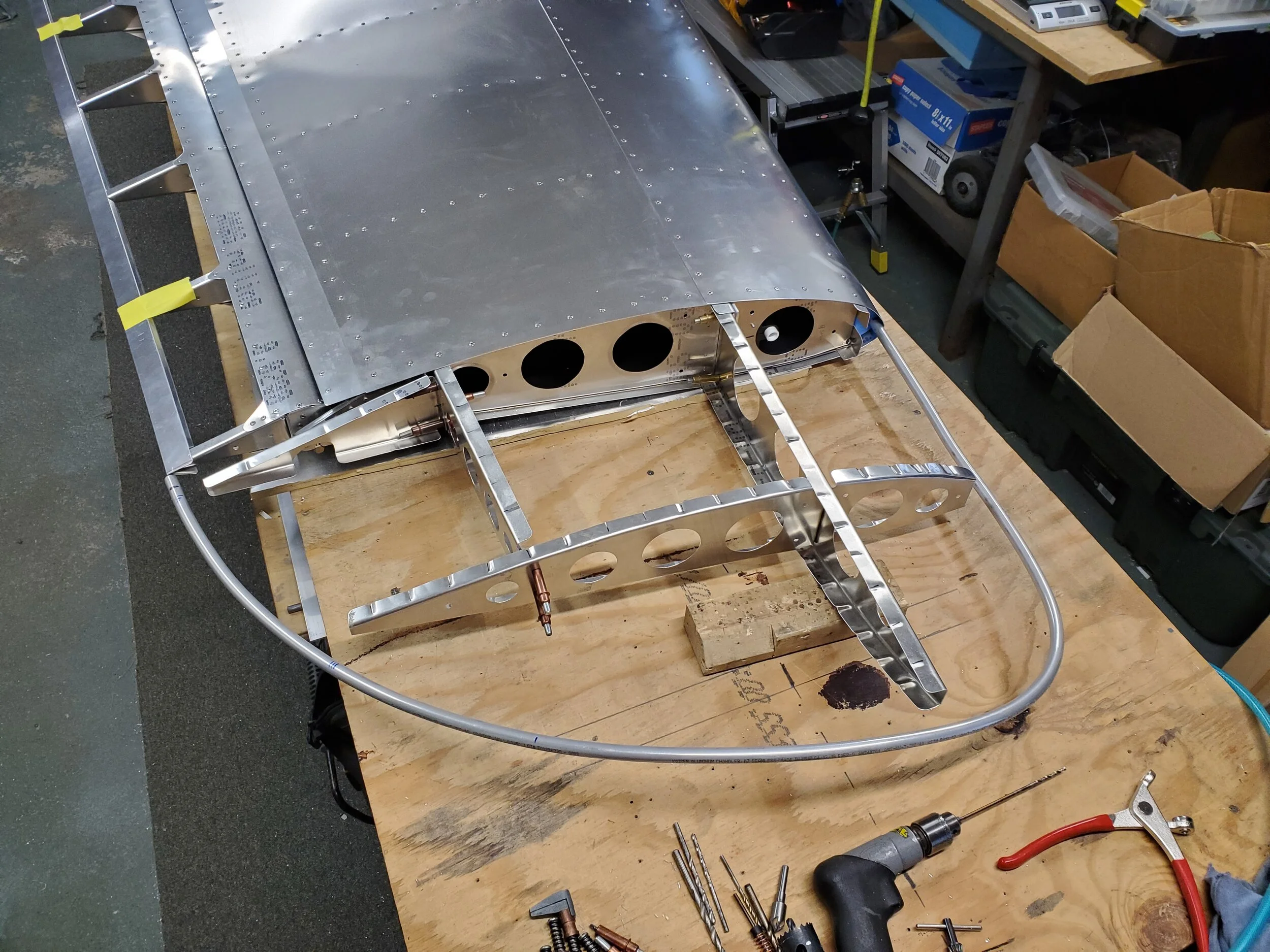
The wing tips were originally going to be composite and just bolted and riveted on. Easy peezy! Well, problem is we were going to be a long time getting them - our buddy switched to making masks and face shields for first responders. Good cause for sure! But it is another major delay we are dealing with. So we thought about it. The real one is metal. Can we do it? After studying the real P-36 wing tip design and the P-40B that we had close-up images of, we decided that we could do a decent job of making it from metal - if we can english wheel a small panel on the bottom leading edge. Another way would be to hydro-form the piece. Turns-out, Curtiss designed the wing tip shape to work with the airfoil - almost all of the top surface and more than half the bottom surface line up with a 3D shaped tip bow and readily lay right down onto the bow. We just had to round the outboard edge to lay against the bow and rivet in place. Hand pounding along a curved steal mandrel worked well. To do the very curved bottom leading edge piece, we purchased a small, vice mounted english wheel and spent some time playing with shaping scraps. Well, it is not easy, but we taught ourselves to wheel soft aluminum sheet. YouTube videos helped. Much better equipment would also help. This was relatively inexpensive and small - it does not take up valuable floor space in our shop - we don’t have any to spare! You get what you pay for though - its much rougher wheel paths, but it did work well enough I think for sanding and painting the tips - not quite good enough for polished metal finishes.
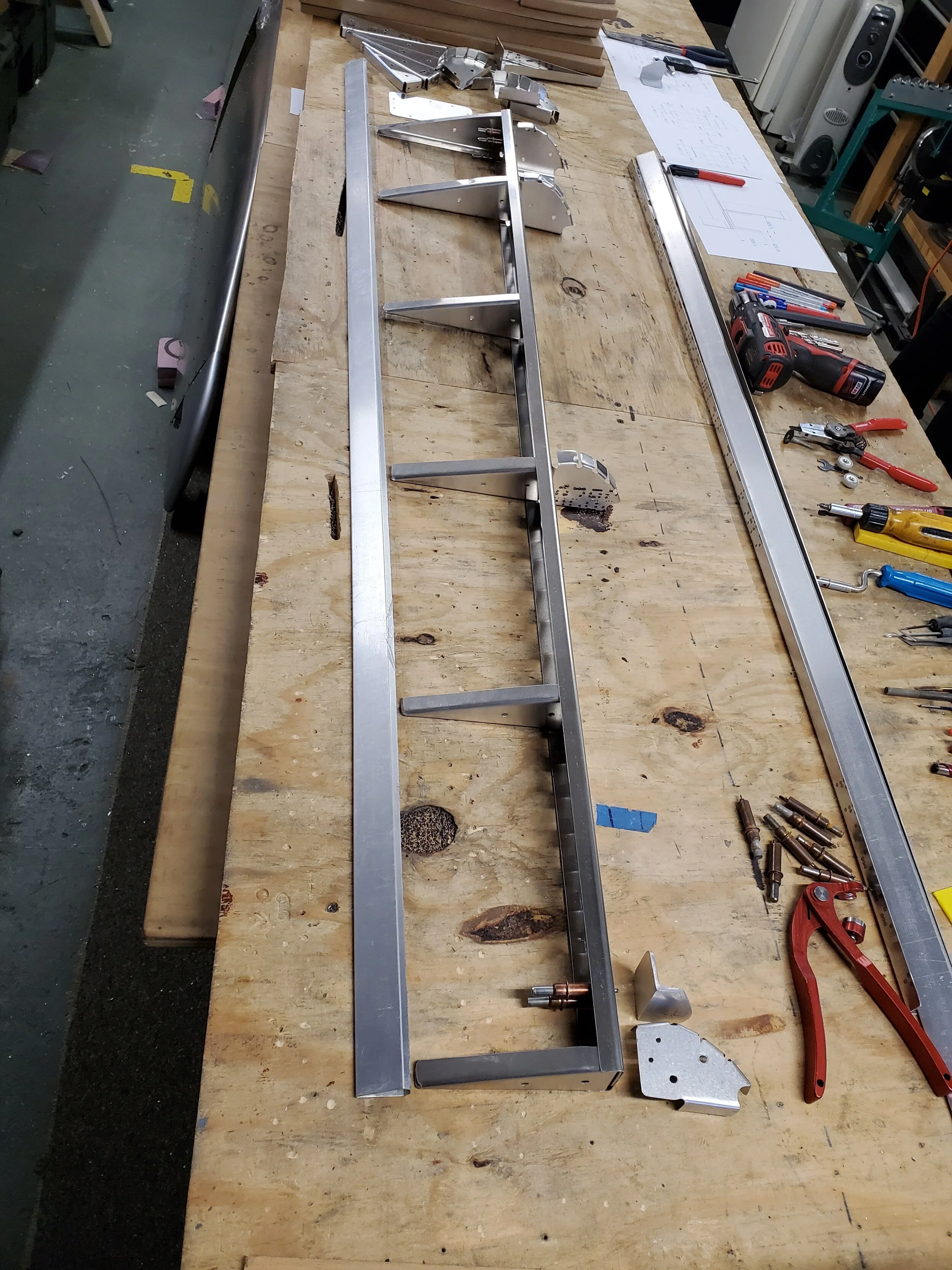
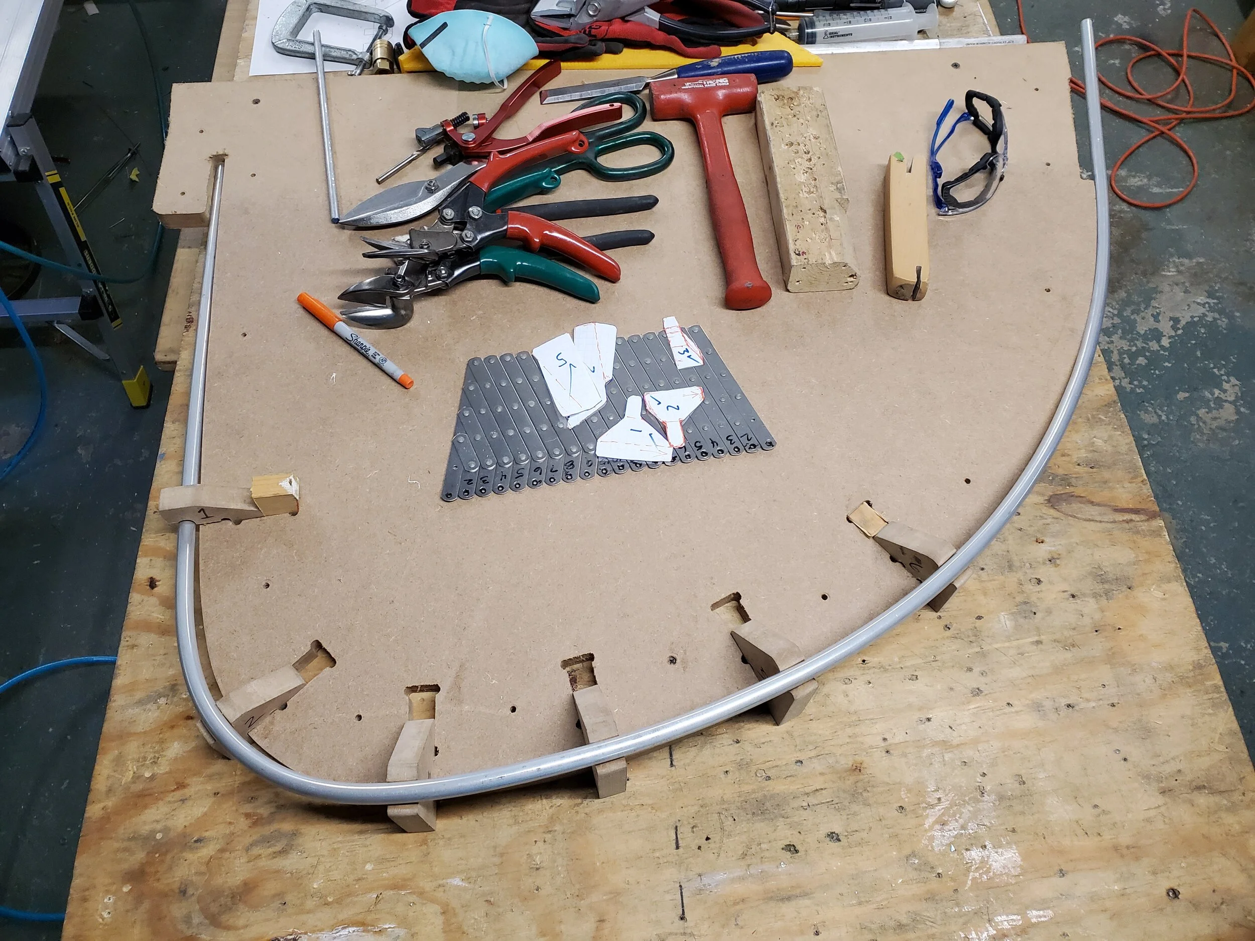
We fabricated the wing tip bows from 3/8 tubing and bending around a wood form. Then added 3D shape to it with wood jigs at various stations along the bow. Hand forming the bow to shape. In and out of this fixture a bunch of times before having it sit perfectly in place. Then we fitted the ribs and short spars parts that make up a support frame for the tip. That’s when we worked the skins and drilled, riveted them in place.
After fitting the last of the left wing tip skins, Scott wanted to make spring retractable tie-down rings - per Curtiss. He designed them to be very similar to the original, but easy to fabricate with our equipment. He also had to design a welding and milling fixture that worked really well. I welded the rings to the print and Scott cleaned them up and added holes on the mill. Then he cut the aluminum mounting bracket on the mill and installed everything. I think they turned-out awesome!
The left wing also gets the pitot mast and head. On most of the early WW2 aircraft, the pitot head was this large spear with a shark fin. We looked at machining it - very serious machining and decided against it. 3D printing was a good option. Scott’s friend is now president of a 3D printing company doing amazing parts for medical and defense customers. He printed our design up on a state of the art printer. It came out looking like it was cast. Just the slightest surface grain - like a #2 mold surface. It’s dark grey plastic resin but can be painted. I fabricated the mount that holds the mast and head to the leading edge. Scott made a bulkhead mount for the 1/4” aluminum tube to pass through the spar web where we wanted it to be. After installing the mount, we could close up the wing tip for good. Each wing tip has a generous access panel for getting to wiring and pitot components. So then we riveted the skins on. Wing done! I think it came out awesome for not being experienced metal craftsmen. And looking at the pictures, the originals were not perfect. Today, the restoration shops are paid millions and make everything perfect and then polished or gloss painted. Back in the day, they were slamming them out as fast as they could.
We then did all the same effort to the right - starboard wing. Mated the wing panels together, added the trailing edges. Made the tip bow and installed the ribs and spars. As I’m writing, Scott is fitting up the leading edge skins on the tip. The main top and bottom skins and tie-down are installed. Got to brush up on my english wheeling again to do that bottom skin piece. Hopefully this weekend we will be finished with the right wing. Then install the fuel tanks!
UPDATE: both wings are built. Second wingtip went well. We are very busy with engine mounts, exhausts and oil tanks for our Verner customers. One needed an adapter plate and Scott milled that out. Getting very frustrated with our UPS Customer Center - the procedures due to Covid. We are now starting to weld up the fuel tanks and have bent the capacitive senders as required for our installation. Can’t wait to see them installed and the wing back on the fuselage - shortly!
All of you - stay safe and keep plugging away at your projects.
p.s.: pictures coming shortly - check back. Down-load issue from our phones.


