Emergence
Scarlett 5Si fresh in the box.

ScaleBirds, Home of the 63% Scale Hellcat replica kitplane project.
Scarlett 5Si fresh in the box.
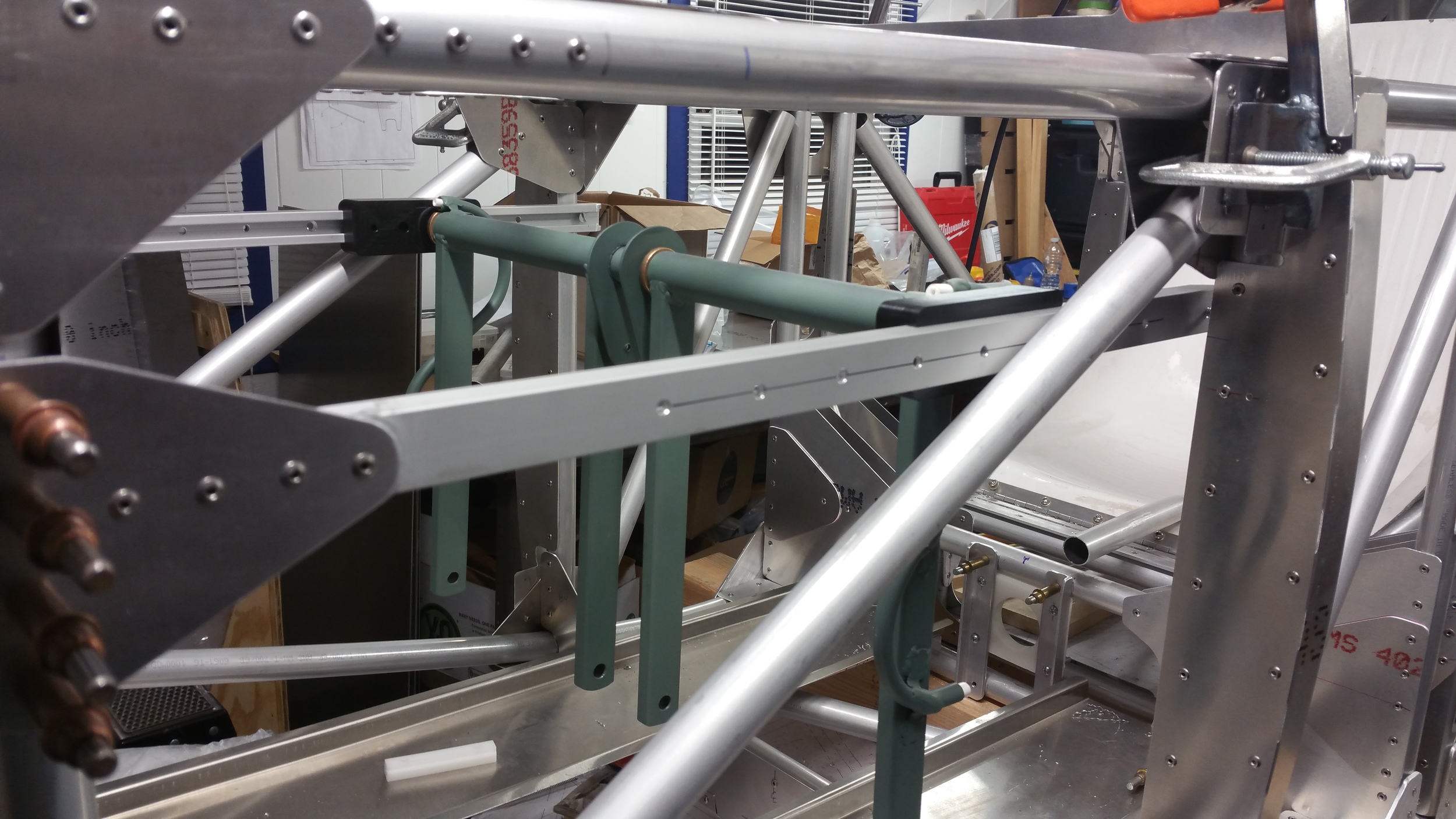
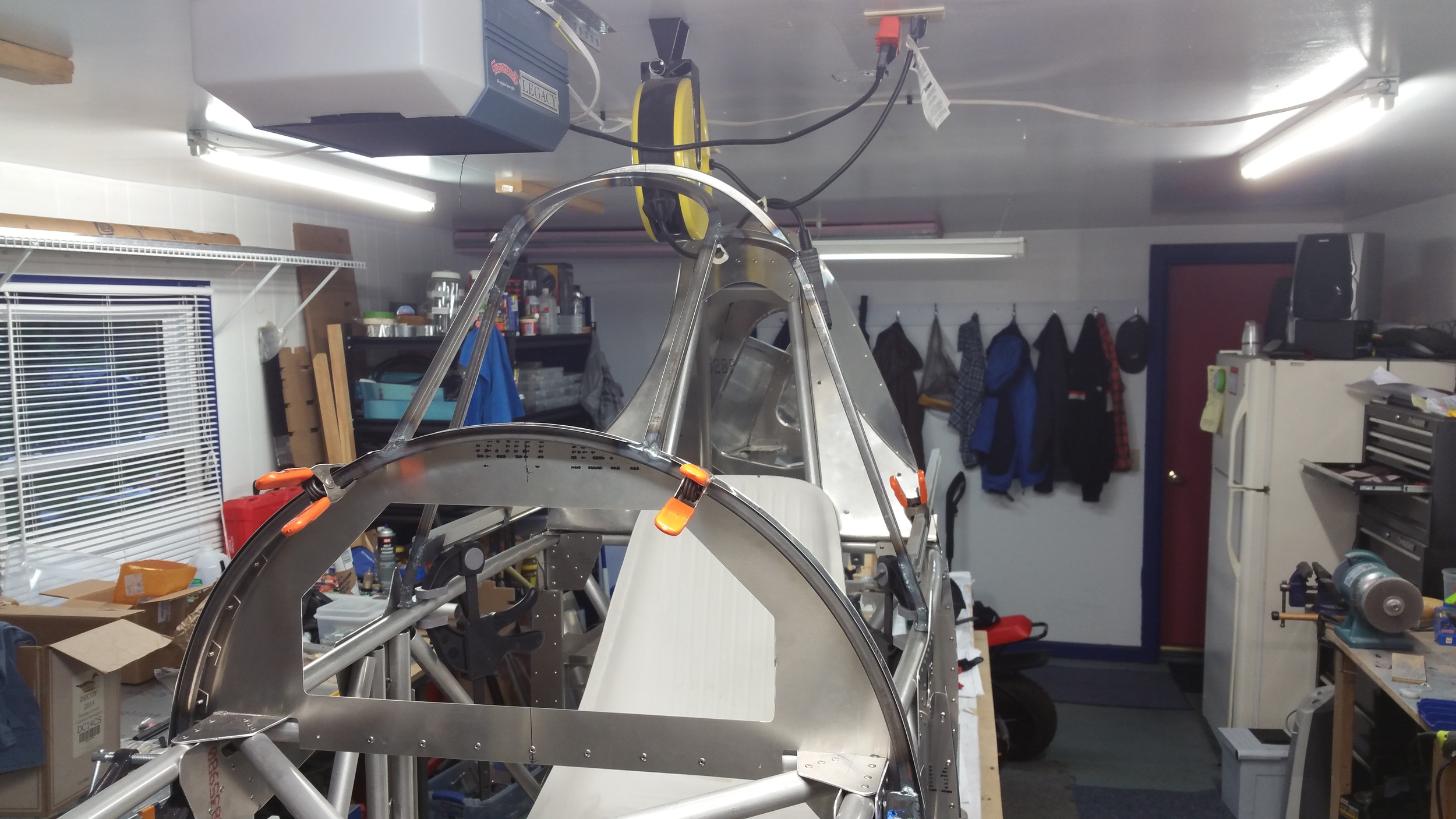
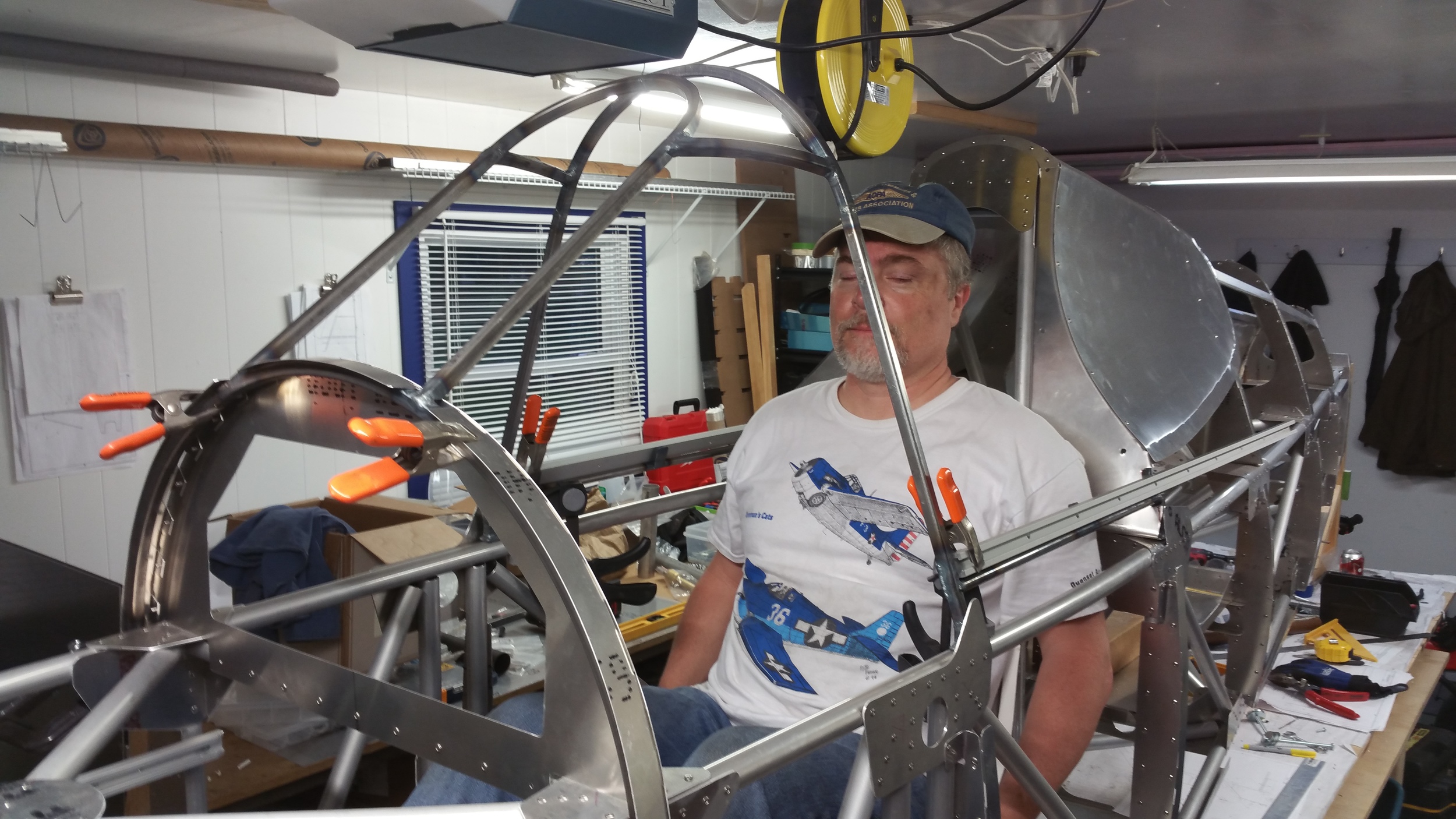
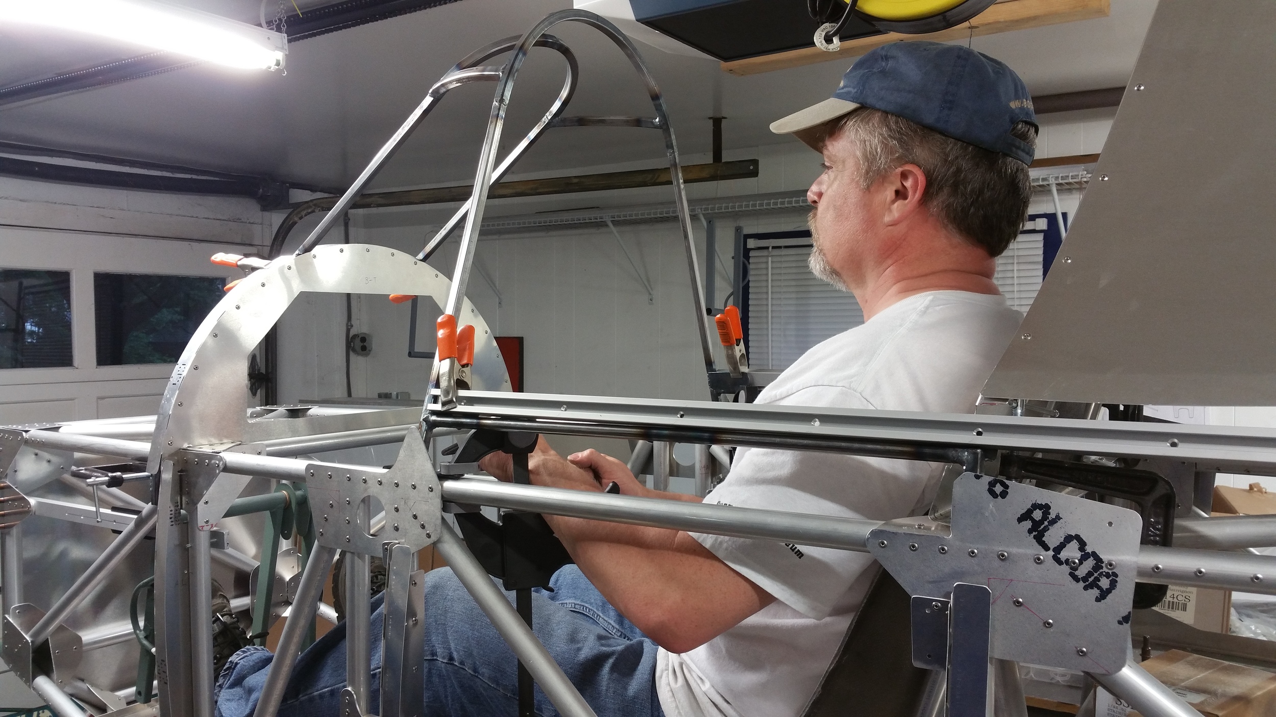
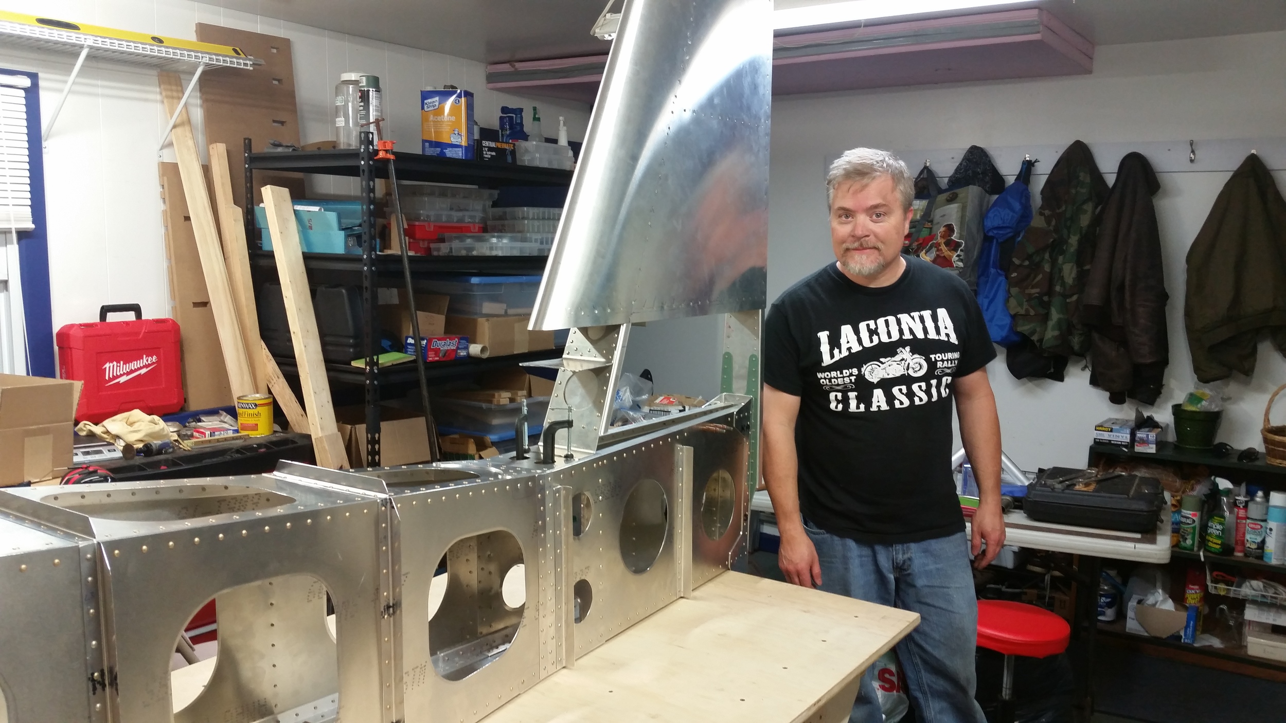
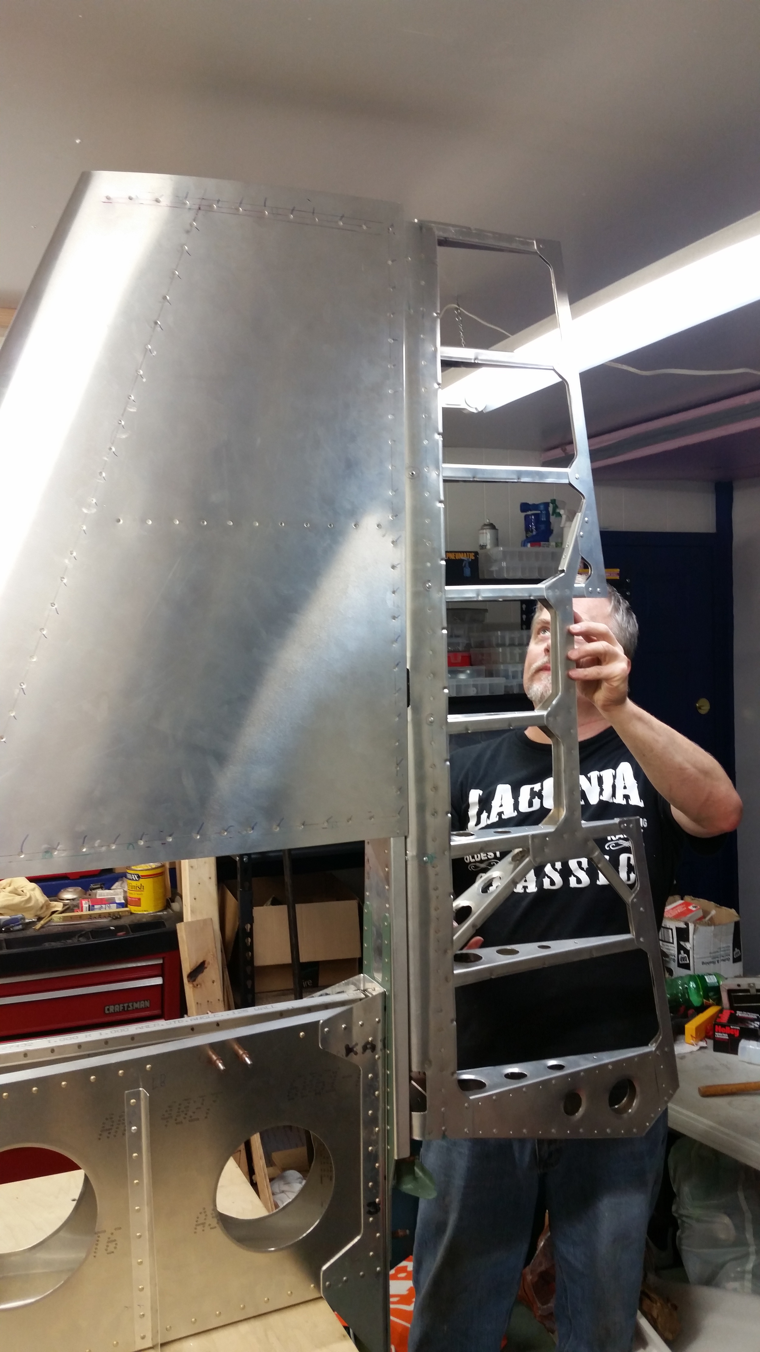
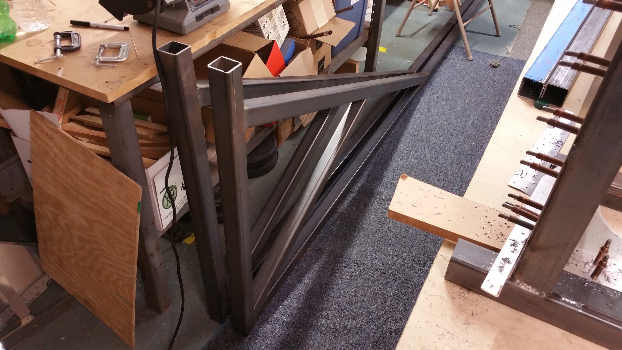
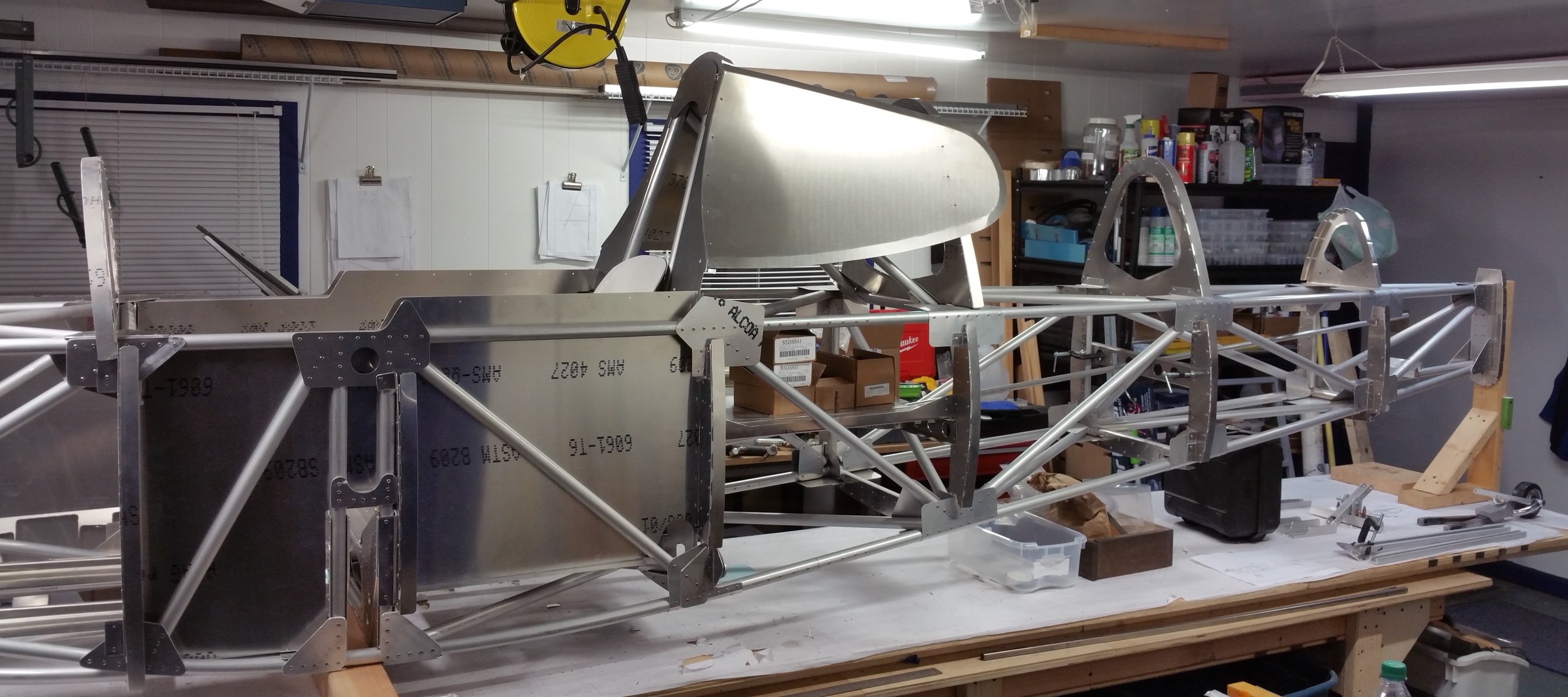
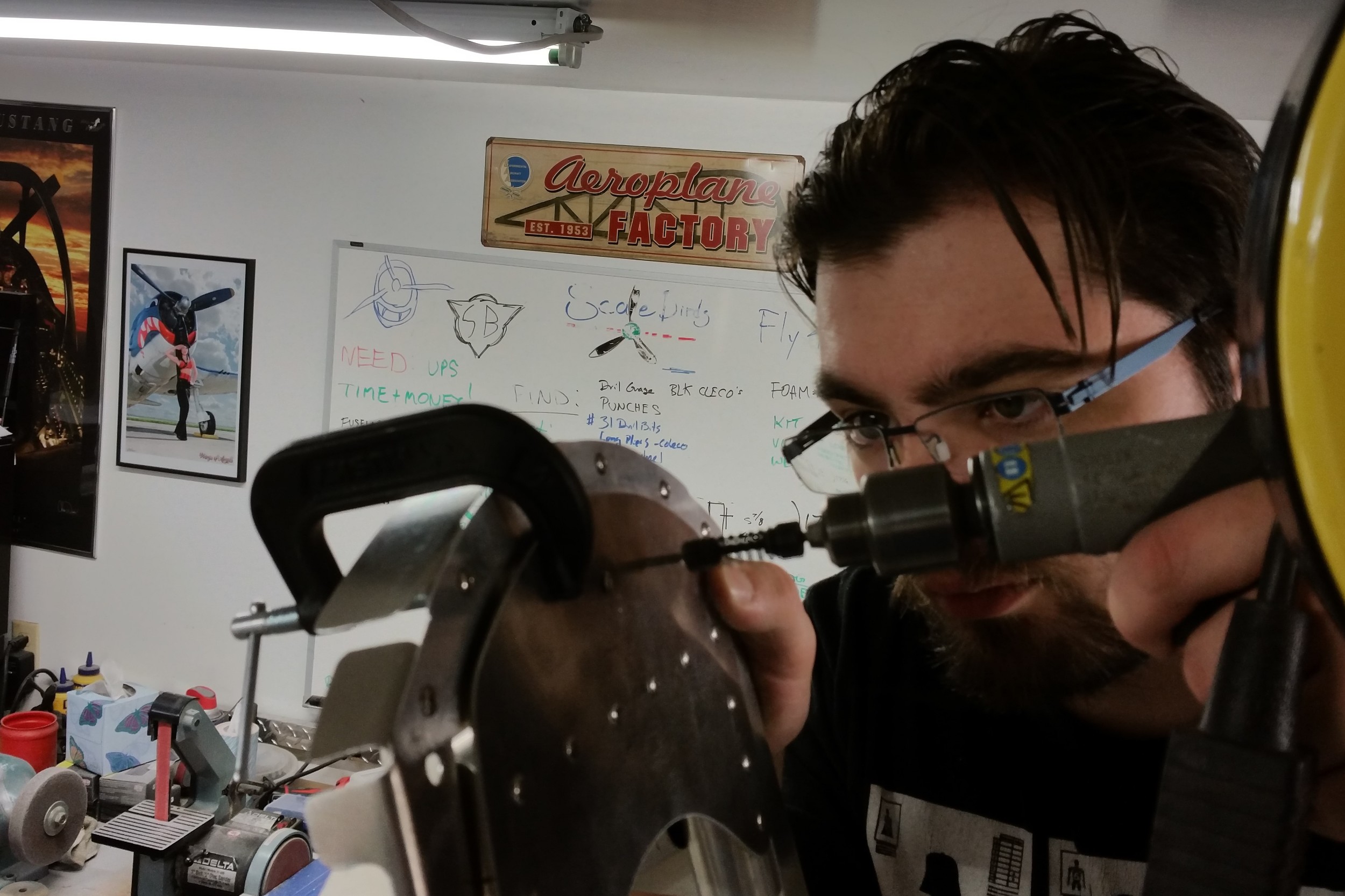
Working on parts again, we have been working on the canopy frame and the controls for the last couple of weeks. The tracks for the rudder pedals are installed directly to the frame, and the pedals hang on a bar that slides along the tracks. The acetal slider blocks and T-nuts that connect the ends have been fitted, and Scott did a great job machining them to an ideal fit. Once we get the pins and hardware we can have the rudder pedals fully installed and start planning the lock-pin mechanism. The forward skins need to have the canopy frame in place for proper fitment. So we cut, bent and welded it all up. I am pretty happy with how it turned-out. Its starting to look like a fighter now! Now we can get the forward skins and firewall cleco clamped in place and all fitted. Our buddy Chris Collins has access to an auto paint booth and we intend to paint the frame shortly. Then we can permanently install the aft skins and controls. We are getting there! Making forward progress!
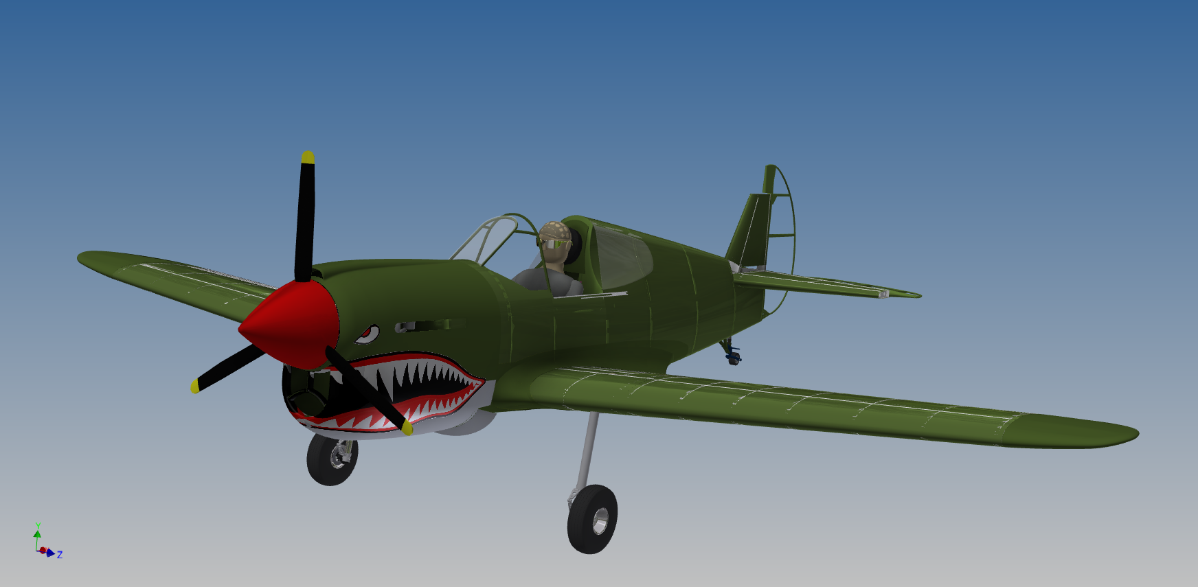
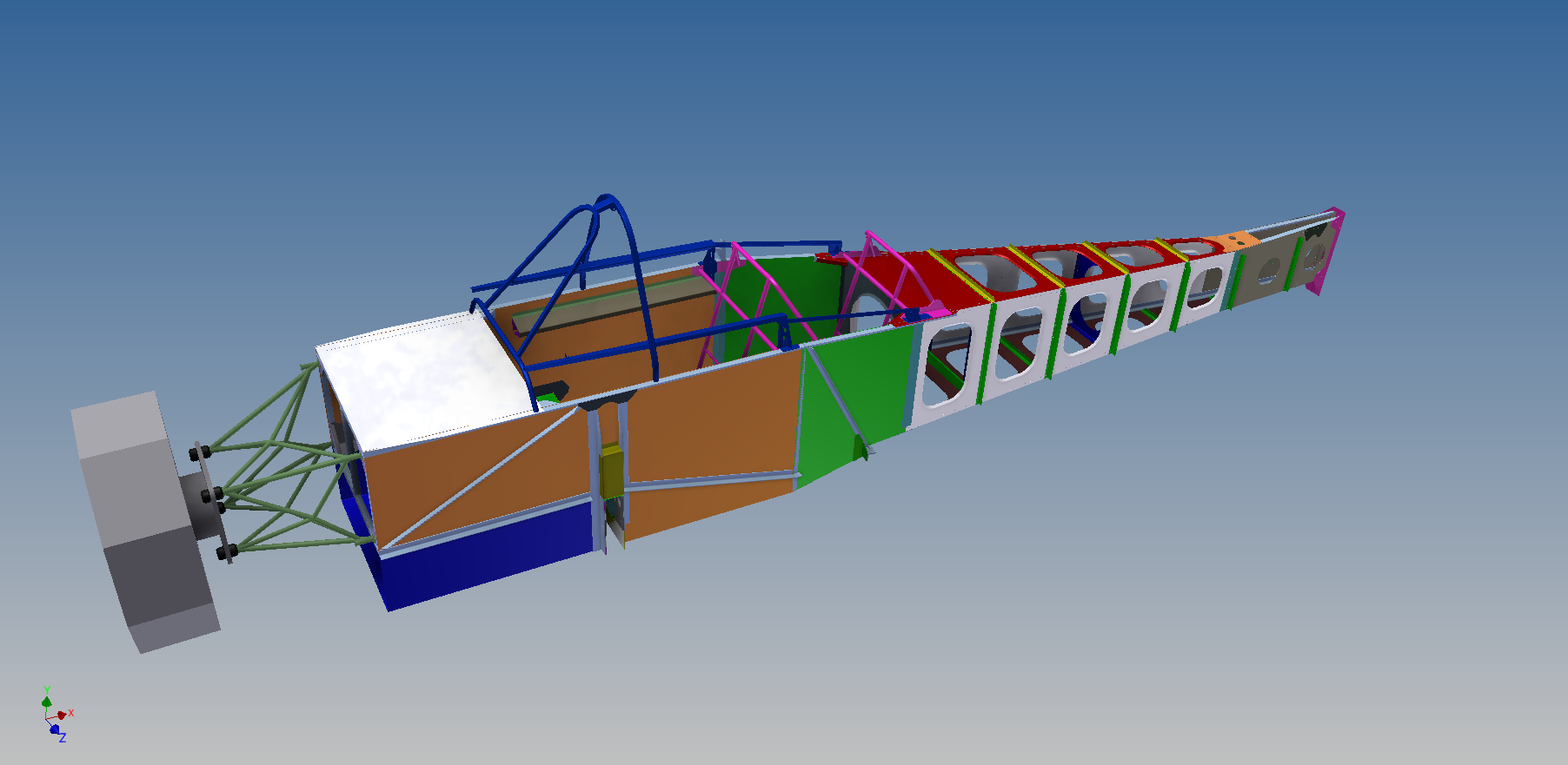
On the CAD design front, the modelling of the wing root fillets has been redone to conform to the latest fuselage, while the track slides and windscreen frame is now part of the model as well. It really adds something when you have the full frame.
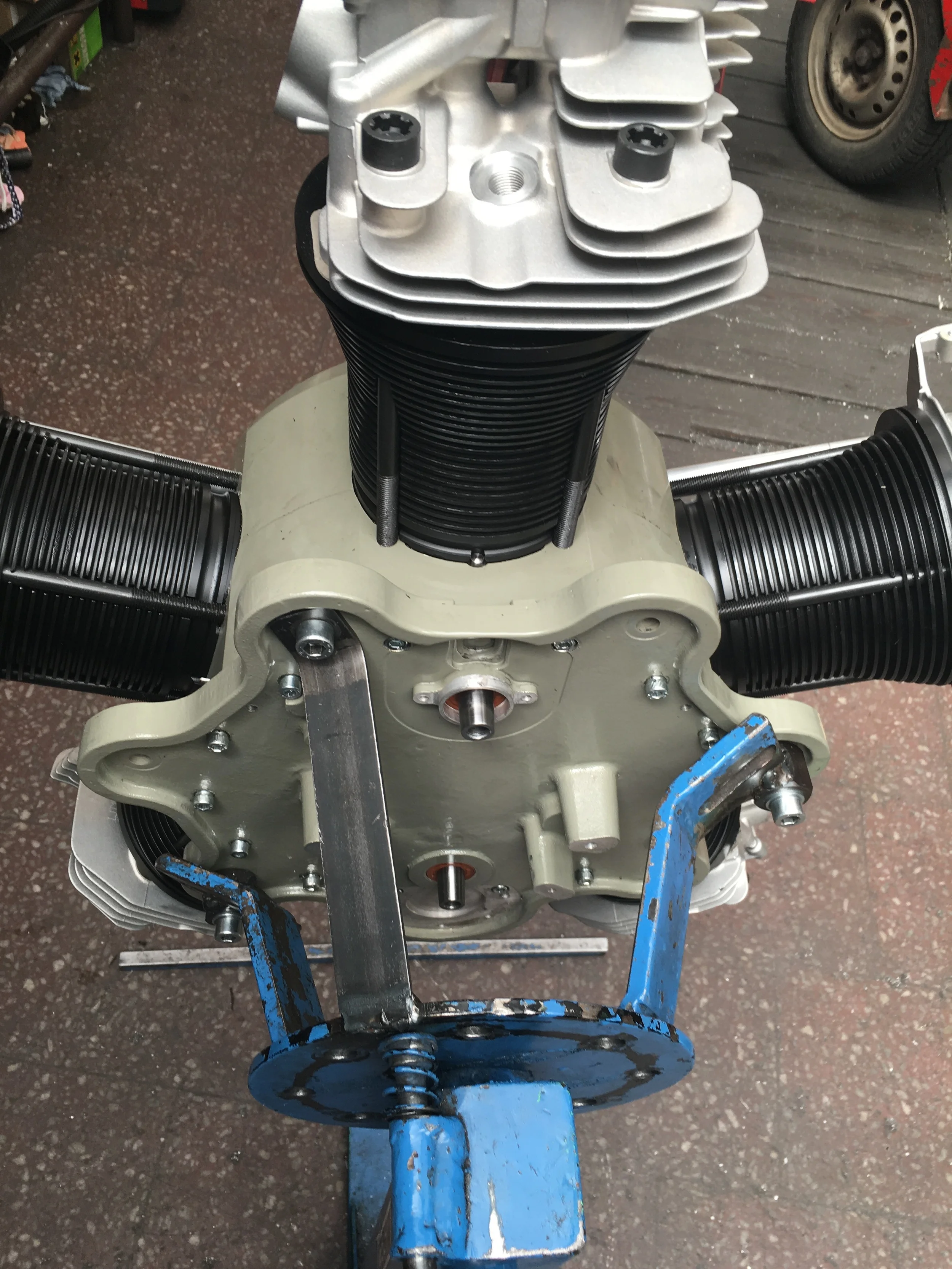
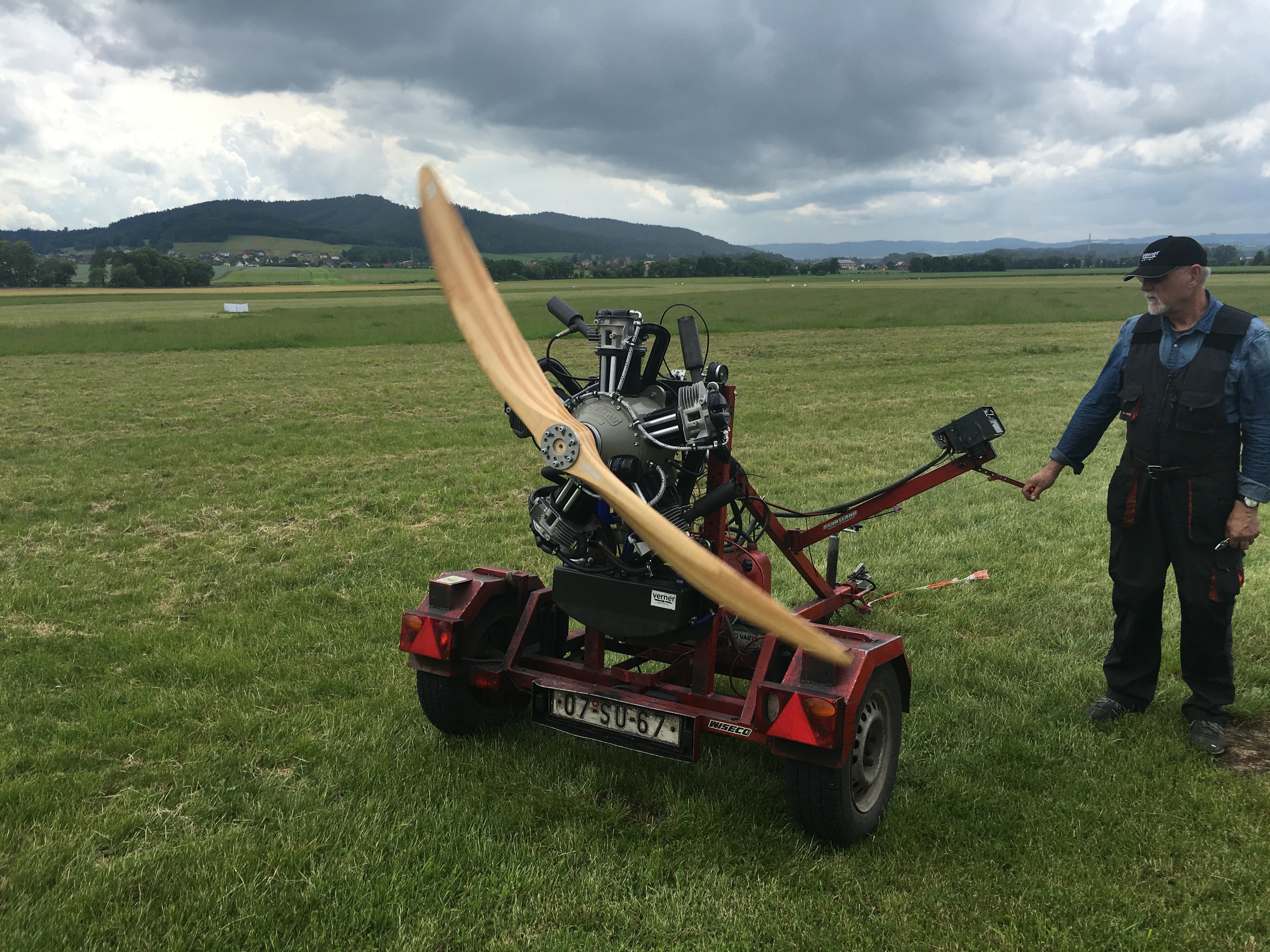
On another front, we ordered a Verner Motor Scarlett 5Si engine to put on one of these planes, and it is shipping soon! Verner sent us some images of the build on our specific motor, so we'll share some here for you:
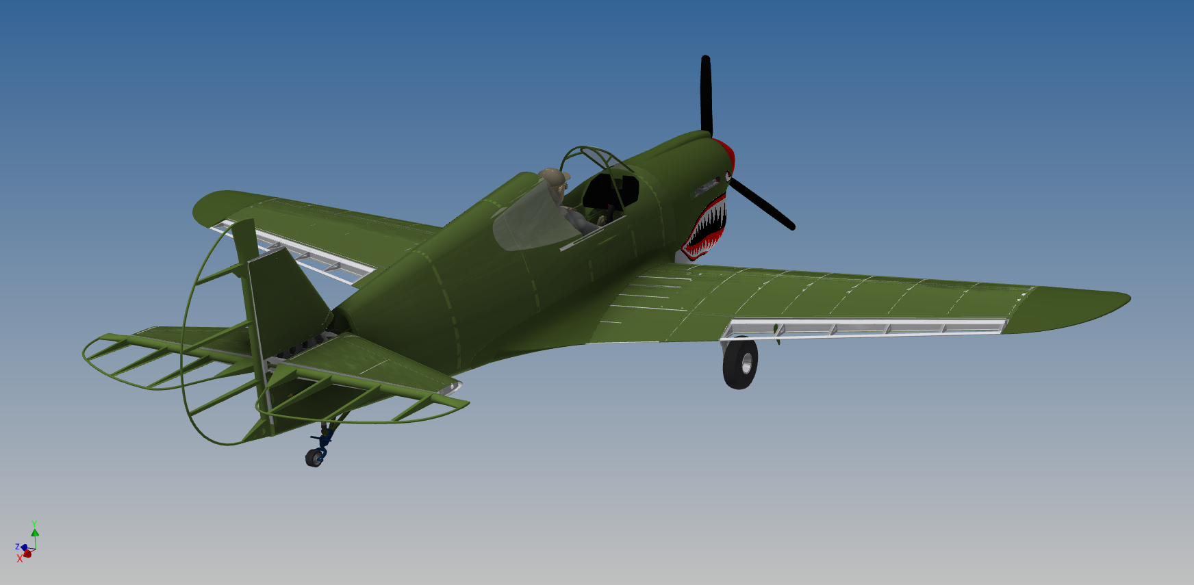
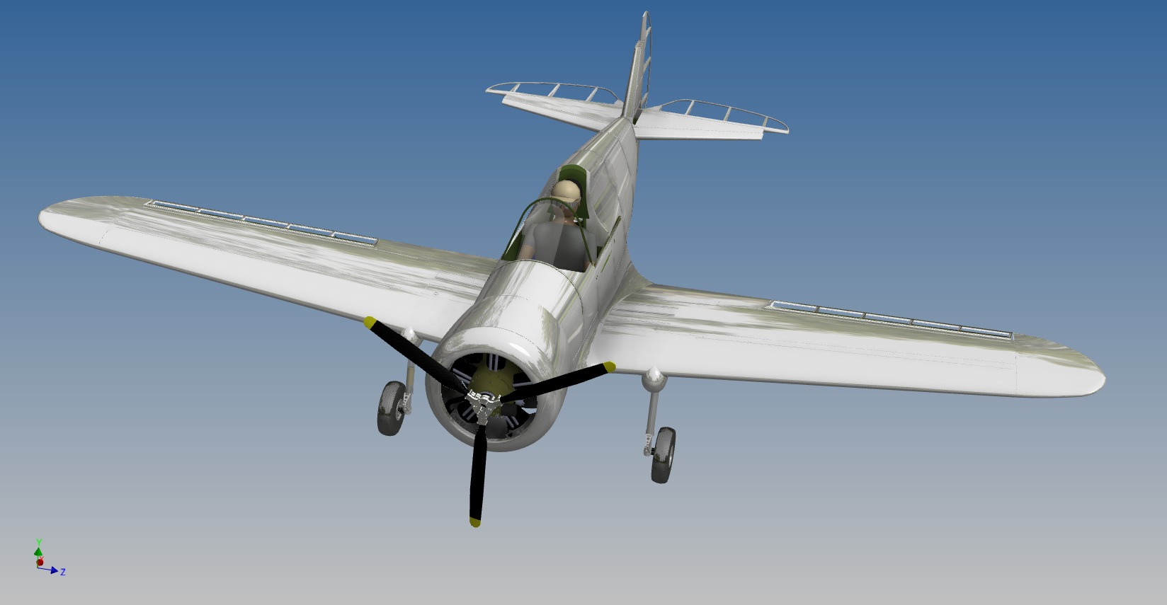
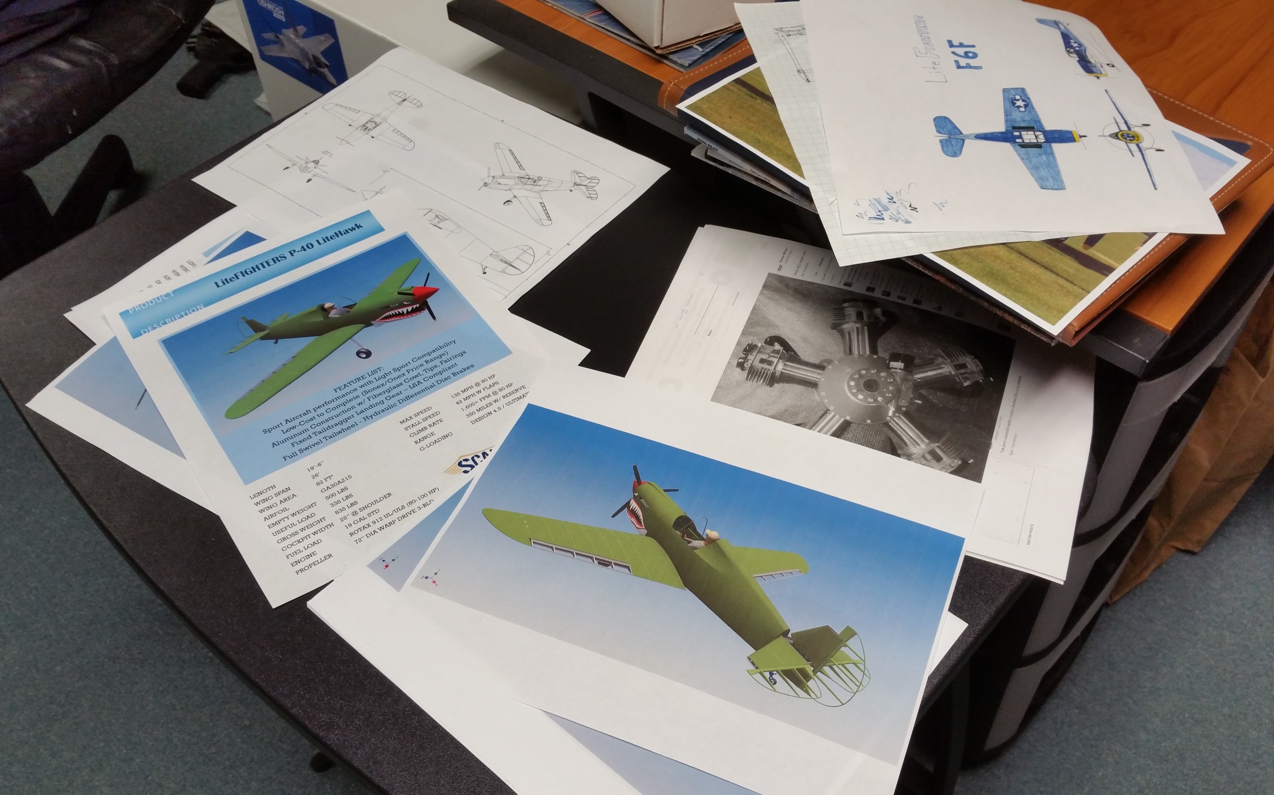
The original intent of this motor was for the LiteFighters F6F Hellcat, but it would be just as home on any radial-powered replica. Now, the P-40 is designed for a Rotax 912, and we don't yet have one. And so, the idea of testing a radial on the P-40 is, well, compelling. We would basically be making the P-36 Hawk. And so we could fly it with a radial and then, just like Curtiss did, convert the airframe to a P-40 with a Rotax once we source it. By then, the Scarlett will be already well proven and ready to go on the Hellcat as the interfaces will be identical between the two planes. Plus, if we were to do this, it would be a very interesting way to get comparison data for our engineers to crunch. Scott did a quick mockup in CAD, so check this out and let us know if it seems like a good idea:
Furthermore, we have been invited to become a Verner dealer for the U.S. market. We are thrilled to be involved! We have needed a small economical radial for our models, in order to make a good number of them really shine, and the Verner seems to be the ideal fit for our size of plane. This deal ensures a consistent supply and support for our future kit customers - as well as those with other projects looking for a radial. Now, I still appreciate the Rotec radials and we will support our kit builders who want them for the Sport Fighters. In fact, we've been inspired by the success of the Radial Conversions RV-8R, I invite you all to go check that out if you have not yet. We've talked with the builder of that Hellcat-inspired RV, and I think there is a lot to learn from his experience.
We are planning to make changes to our web site to feature all that ScaleBirds will offer: LiteFighters, Verner Motors and the continuing adventures of our Two-Seat Design and Build. Stay tuned for the changes and updates!
Time is high for a little update, so lets get right into it.
Progress on the LiteFighter development drives on, with the immediate goal to get the fuselage for the P40 fully clad in aluminum and ready for the next step. It's a multi-front effort to get there, CAD is being done at the same time as parts are being made and fit. Since this is an initial build prototype, there are a lot of things that are being figured out on the model first, then worked back to the computer. I suppose the best way to cover what's going on is to dive into each aspect and go to brass tacks.
CAD design:
Being a CAD guy, I enjoy dealing with the 3D modeling on this aircraft project. And I enjoy taking a design from the screen to the workbench. But having gone through plenty of design over the years I'm getting to be more pragmatic with what needs detailing and what doesn't. In some cases its quicker and just easier to cut parts out by hand. But there are still a lot of parts on this thing where the accuracy, complexity, function, or visual detail of the parts, really do justify the time taken to make sure everything is fully realized in the CAD model first.
As the 3D model was originally made when we intended to have a fabric-covering, some stuff has been done in the real world and then I've had to backtrack those parts into the CAD model.
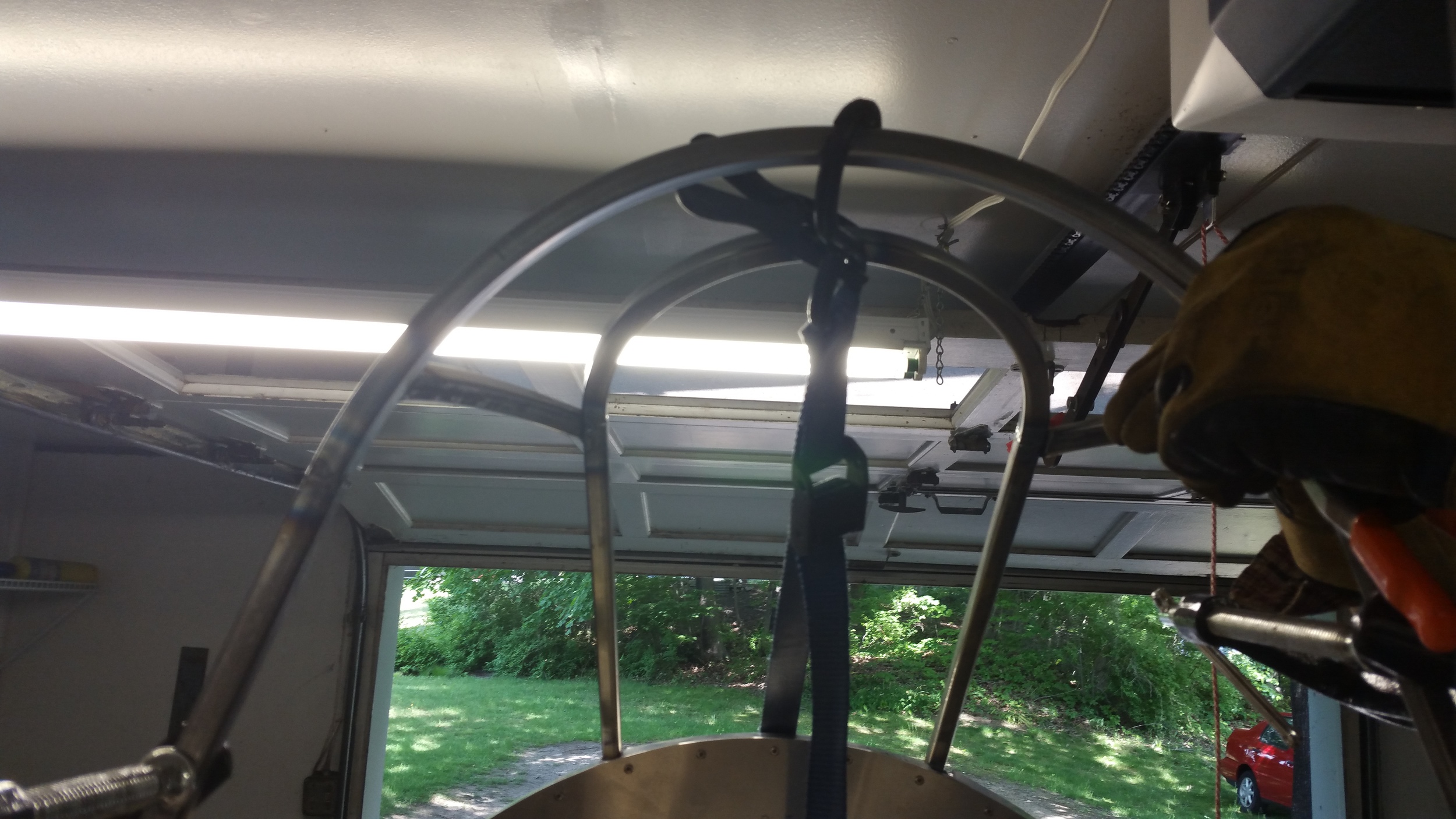
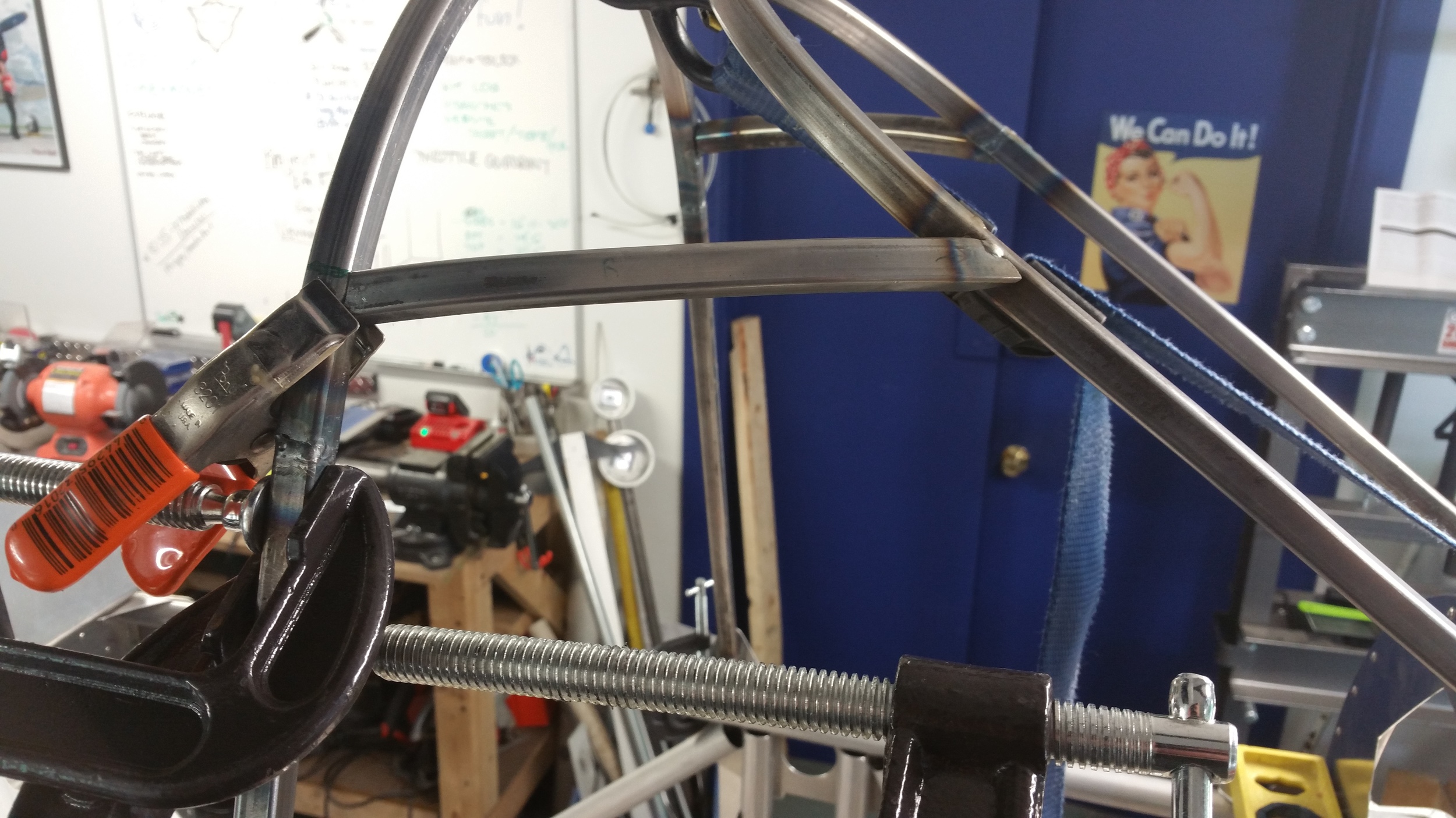
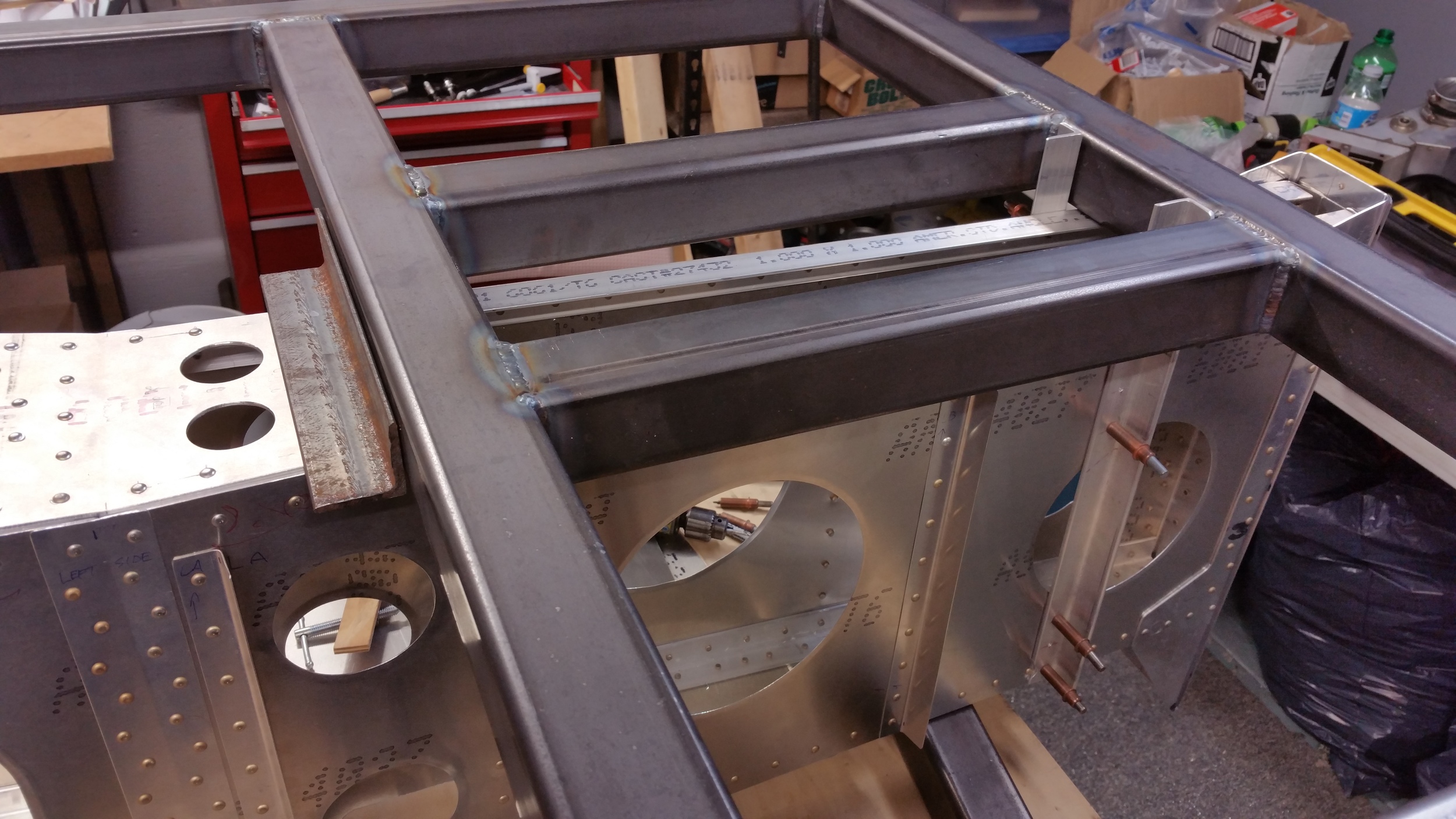
As things progress, the windscreen frame and tracks are likely the next parts to be fabricated so I've had to spend some time coming up with a decent set of geometry. Actual construction of the windscreen structure was a subject of discussion, and while there's undoubtedly some great ways to do it, we settled on a method we already knew and liked from the Hellcat mockup; using 1/2 inch steel square tube. It's easy to bend and form, and to weld into a single structure, so while we can revisit the concept in the future, for now it's simple and its strong and it works.
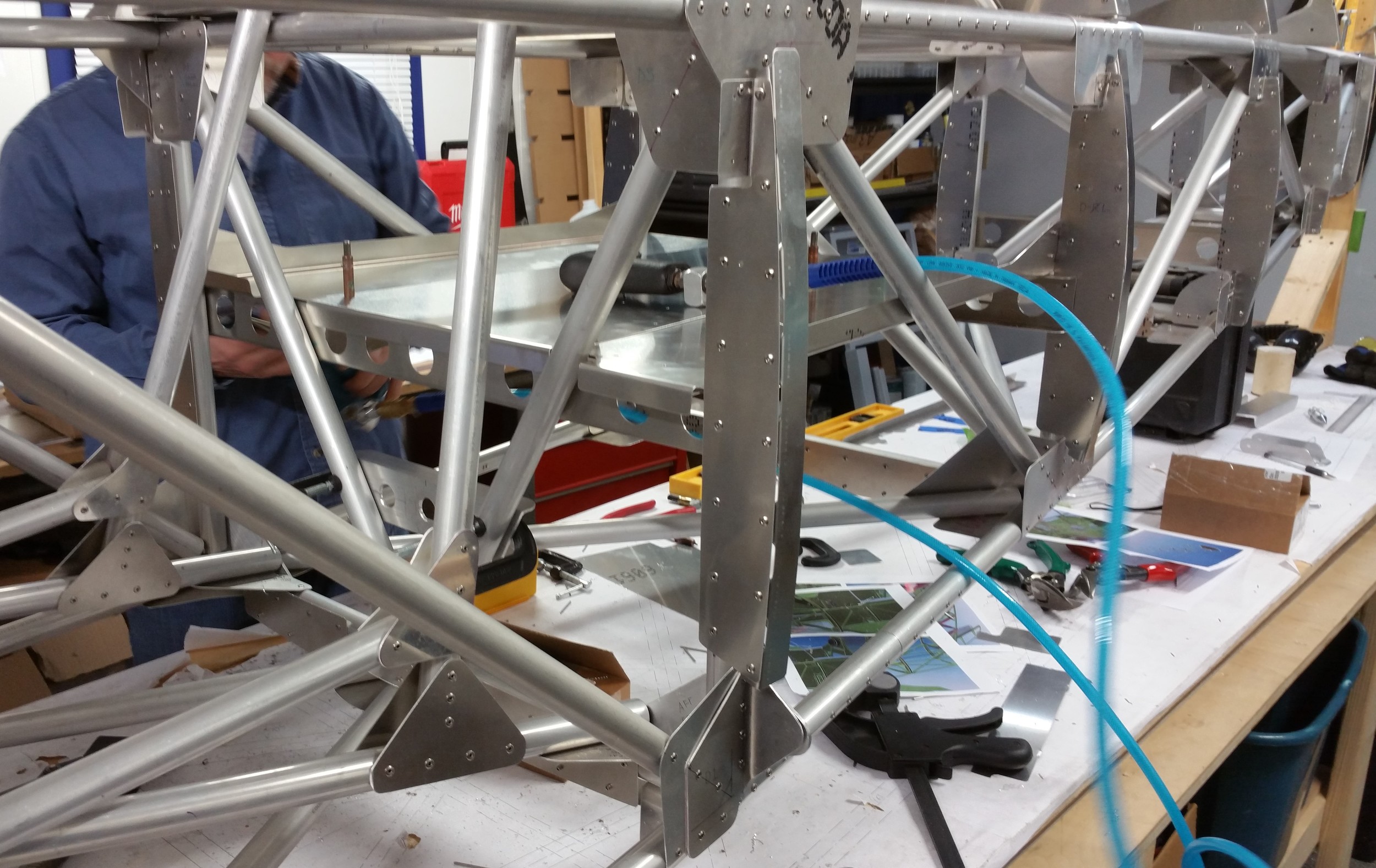
Been making parts fast and furiously for the Lite Fighters. We added the bulkheads to the P-40 frame and have been working on all the internal components. Again, as we are making all these parts we are making two sets. So the F6F will mostly be installation work. We only have so much space so we are concentrating on the P-40 first. Controls, baggage compartment, rudder pedal assemblies, tail wheel assembly and mounts, etc... It will get the Rotax 912 and we have a friend with a brand new - but 15 year old 80 hp engine we can install - after we get it torn-down and all the rubber parts replaced. The design will handle any of the 900 series Rotax motors - well, the new 915 may need to be engineered as the inter-cooler sticks back too far. Anyway, the 80hp will match-up with the F6F and the Verner 83 hp 5 cylinder we are ordering soon. It will be interesting to compare the two for performance.
Speaking of performance, we are seeing some very remarkable preliminary numbers. Flight testing will certainly tell the tail, and I don't want to be too optimistic. Lets just say that the P-40 will climb really well - exciting even - and should cruise at the high end of the LSA speed limit on the 80 hp Rotax - we may have to limit the speed with prop adjustments and other tricks. Of course, if built as an Experimental Amateur Built, no speed limits and restrictions. We are also looking at other engine options for the In-line models. The Geo metro engines from Air Trikes and AeroMomentum should be able to fit our P-40 cowling as we intended this to be so. However, we need better dimensional data from the companies to be certain. Doesn't everyone have 3D models now??? The Verner powered Hellcat will climb like a home-sick angel. It has double the torque of the Rotax with the right prop, and there is room to have a large diameter prop on it to use that torque. The drag the F6F will have due to the cowling and barrel-like fuselage is not easy to calculate with our capabilities. So, we will have an idea but no way of knowing how close we are till we fly her.
Also want to re-state that we are not killing the 63% Hellcat - it is just on hold for a bit. We need to get more resources to continue it. We have numerous options but chose to make these Lite Fighters as a way to get us started small and learn the business. I mentioned on the Homebuiltairplanes forum that this is a means to an end - we intend to complete the 63 and other larger two-seat models. Having both product families will be a good thing! Checkout these pics, we will update the whole website soon, but not a huge priority right now. So hit the News page and follow us here. Thanks!!
The ScaleBirds project has been through some significant twists over the last 8 months. Significantly, the 63% 2-seat F6F Hellcat we have shown development on up to now, has been put on the back-burner. A reason for this is time and resources; it takes a lot to engineer an airplane at this level. It is coming along well, and we fully intend to finish it in time.
But we are not stopping our project. We are working hard as ever to develop something which I think is too good to pass up: a simple, single-seat, fun-scale replica line - called Lite Fighters.
Lite Fighters will be a great kit for the Warbird enthusiast who would consider, lets call it as it is, a Sonex type project. Very economical to purchase and operate, simple tool pull-rivet construction, they will be very sporty and aggressive, but still designed for low-time pilots, light sport and purely recreational pilots. As the name suggests, these designs will comply with the current Light Sport Aircraft regulations and will include fixed landing gear (or optional retracts later on!), and utilize a ground adjustable propeller, 80 to 110 hp engine options, possess mild aerobatic capability and be of modular all-metal construction. As before, our two-seat 63% F6F will be a great choice for someone who wants a more all-around type of kitplane, with larger engines, serious cross-country ability, and serious detail, packaged in a warbird replica. So these will both continue forward as two equally viable design lines.
The good news is we are making huge progress on the Lite Fighters! The first two fuselage frames are complete, and we are building-out the first one as a P-40 Warhawk and the second frame as an F6F Hellcat. Our design is still modular, and at this level of detail, almost all our parts are standard. Thus most every part we design, we are making at least two sets. So for now you will see the P-40 coming together, but the F6F won't be too far behind it.
See our pics and follow this project with us.


We finished the testing in August and you may start to wonder – what the hell were we doing since then??? It’s the end of January 2016 now. So sorry to have been absent, but we've been working hard! We have been back to the lab again, doing a lot of detail designing and modeling. We’ve taken the lessons from the load testing and empennage builds, and been busy incorporating them and fleshing-out the design of the whole machine. Lots of small changes, and a few big ones! Our whole design team went on a field trip to Titan Aircraft in Ohio in September. John Williams spent over four hours of his weekend with us talking shop, showing us his whole operation and how they make every part. John was very encouraging and interested in the Hellcat. He is a real presence in the replica fighter world today as you all might well know, and we learned a lot from him. A primary reason to for the visit is that after some looking at it, we intend to leverage the landing gear components from the Titan 51 as a base for our own gear. The landing gear of the Hellcat impact the layout of the center section in a big way, and without a solid design for them we can’t proceed with the rest of the wing.
We did get another distraction this fall in the form of more equipment. My son Scott decided to buy a small vertical mill and convert it to CNC. This “two week project” turned into 6 weeks or more of tinkering and fabricating. Usually projects just do that. This mill is no Haas or even Bridgeport, but what we need is the ability to machine small, complex parts without blowing the budget. In fact it’s quite a nifty little unit called a Precision Matthews PM-25MV, sold by Quality Machine Tool and Scott purchased a separate CNC conversion kit from a guy going by ArizonaVideo99. It was a quality kit but more DIY than I was expecting thanks to the tolerances on import equipment. Scott decided after getting the thing working and crashing more than once, to go ahead and wire-up good proximity sensors. After two rebuilds it’s almost done now – just one or two cables to go. Then we need to spend time getting used to what it can do. But sorry to say, we didn't make more parts for the Hellcat, so we’re looking forward to get back to that this winter. Back to work!

The tail frame is now finished and tested! We’ve been busy pushing to finish the sample frame so we could find out if the design held up as expected. We would have been done sooner except, well, a little thing like OSHKOSH AIRVENTURE 2015 got in our way. It was a great event and we learned a lot and met some cool people. We’ll have more on that shortly. It did put us back a bit though. Also as always you run into some delays for personal reasons and everybody in the team is super busy at home. Anyway, we did it!
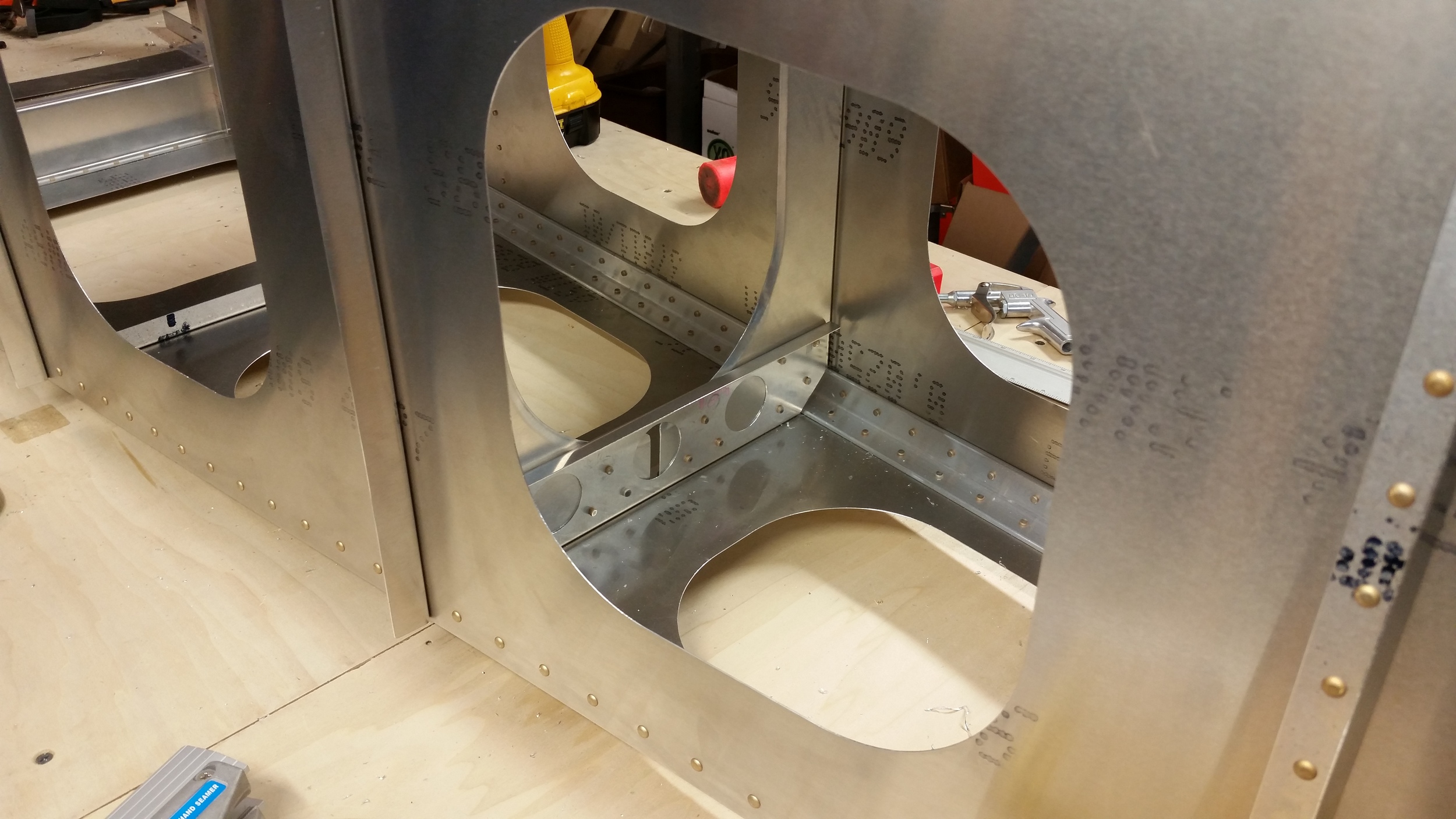
First, we finished the tail frame with some bulkheads and hard mounts for the horizontal. The bulkheads were originally to be single piece with large cut-outs in the middle. Well, if you have a precision CNC bending brake, or a big press with forming blocks, you can do that and it will all fit up perfectly. We don’t have one of those, we have an eye-ball and hand adjusted bending brake, which meant that even with much care there was a little misalignment. So, realizing why other contemporaries seem to have mutli-piece bulkheads, we changed ours to be built with multiple pieces in a picture frame – like the Sonex and other designs do. This method worked out perfectly, as each piece just mates to the skins and then is clamped together for drilling and riveting the corners together, square and happy. Then as mentioned there are the mounting brackets for our horizontal/test load platform. The original design was probably fine, but it had a few potential flaws that could be avoided with a simpler design just using some L-angle. This new approach comes out very rugged and while we had lightening holes in the wrong spot, that doesn’t really matter. The vertical on the other hand mounts up to a heavy-duty end bracket that ties the sides together. The ideal U-bend form of that plate was going to be a nightmare to bend with our limited shop tools so, we made it two pieces and hammer bent each side in a vice with a forming block. It’s not a bad looking install even so, and structurally it really made the aft end super solid.
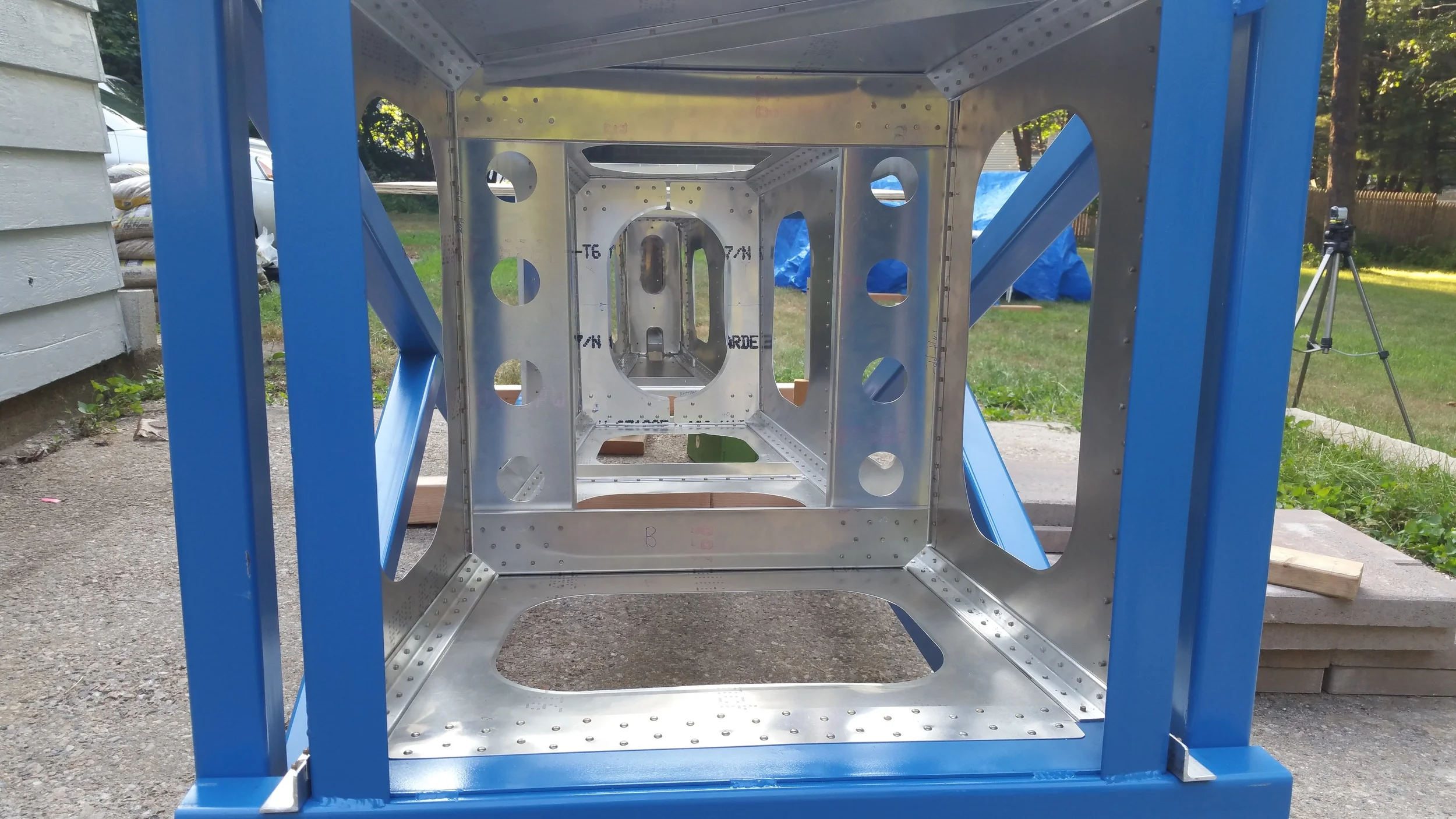
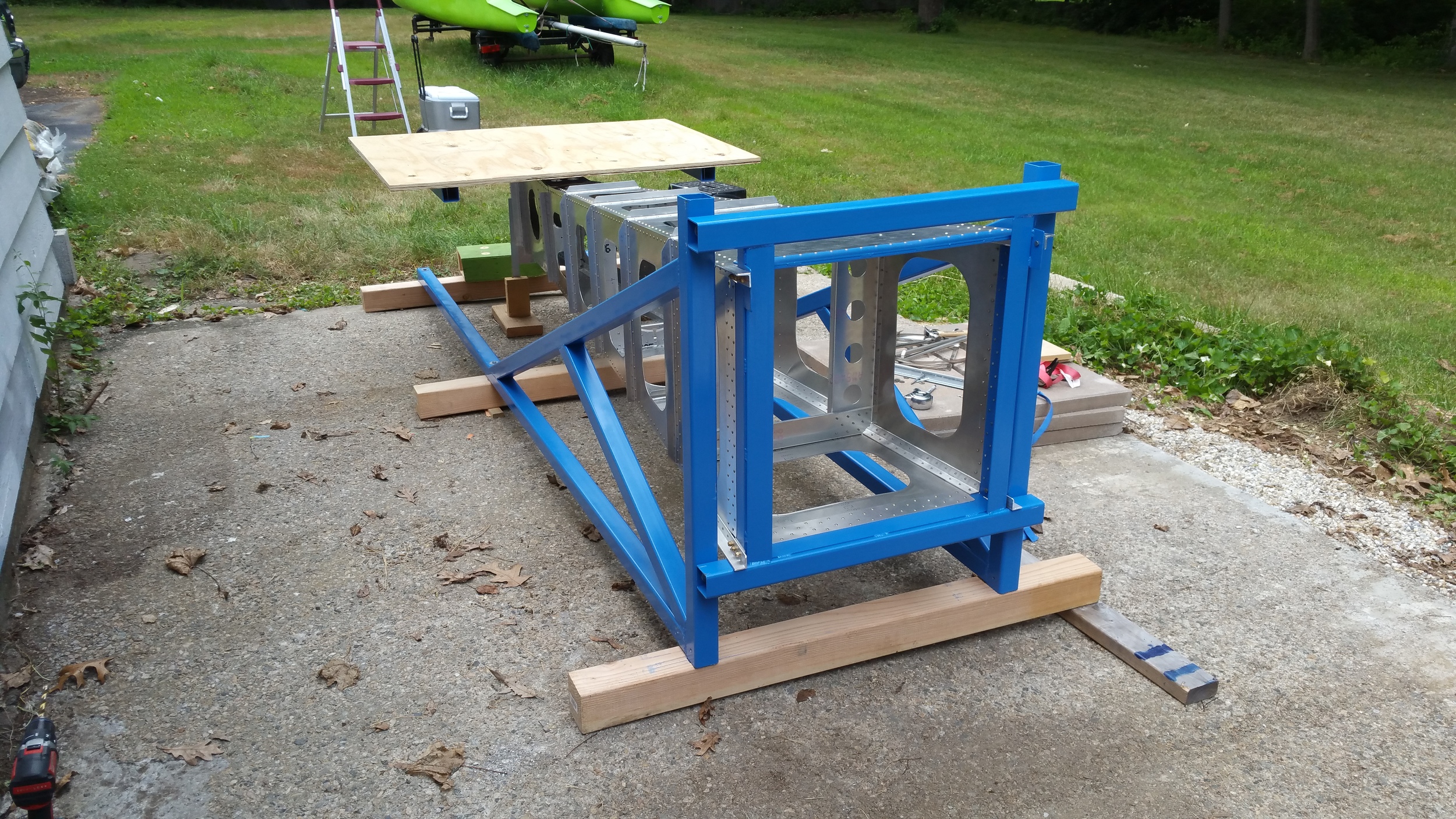
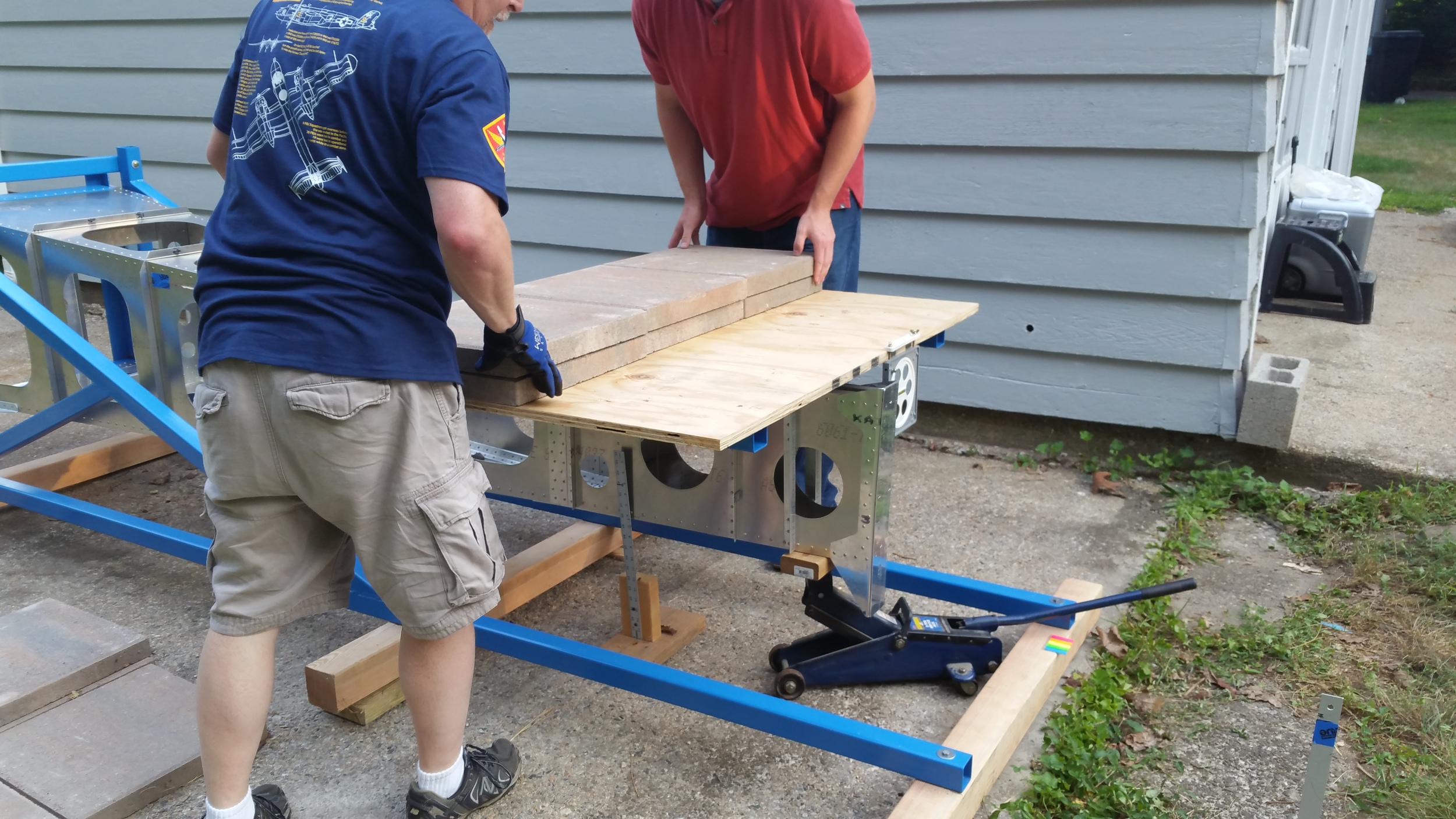
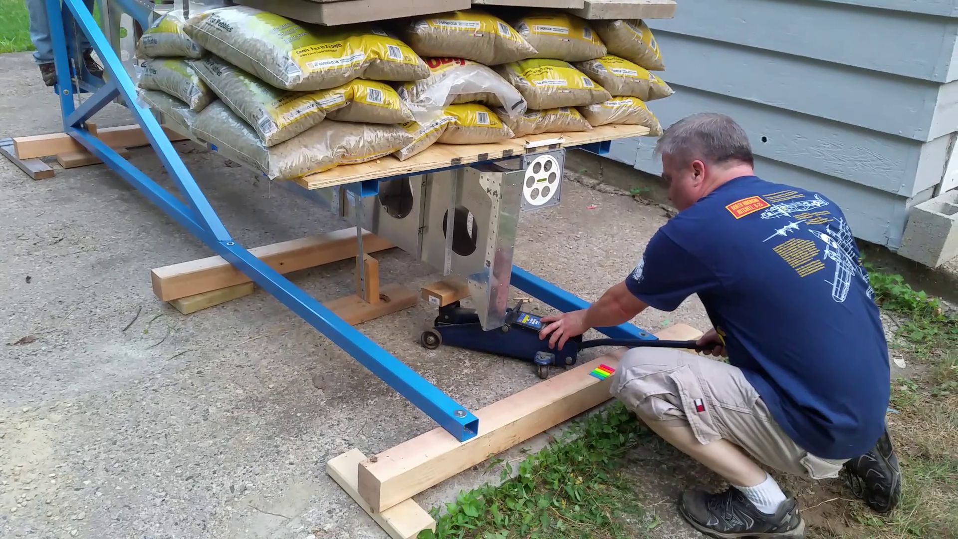
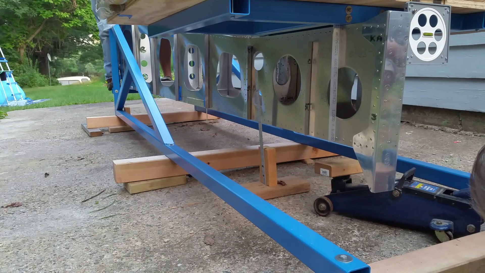
When we finished the tail frame, we needed a test fixture to perform the load tests. We designed and built a frame of 2.5” square steel tubing to support the tail off the ground and keep it stable. To mate the test article to this test fixture, we made a mounting adapter frame. This was a picture frame of steel tubing and plates to bolt and rivet into at the front of the test article. This mounts exactly as the fwd fuselage frame will do. Then, we built a load platform out of the same square tubing and capped with a deck of ¾ plywood sheathing. This is mounted exactly as the horizontal will be and was easier to stack bags of gravel on than the horizontal would have been. Once everything was welded up, it was primed and painted a Rustoleum Rattle-can Blue. When dry, the mounting adapter ring was then riveted and bolted to the test article – permanently – just as the forward fuselage would be. The pieces were set before Oshkosh got in the way. But once we got back it was time to bolt the final assembly together and put it on the pad out back.
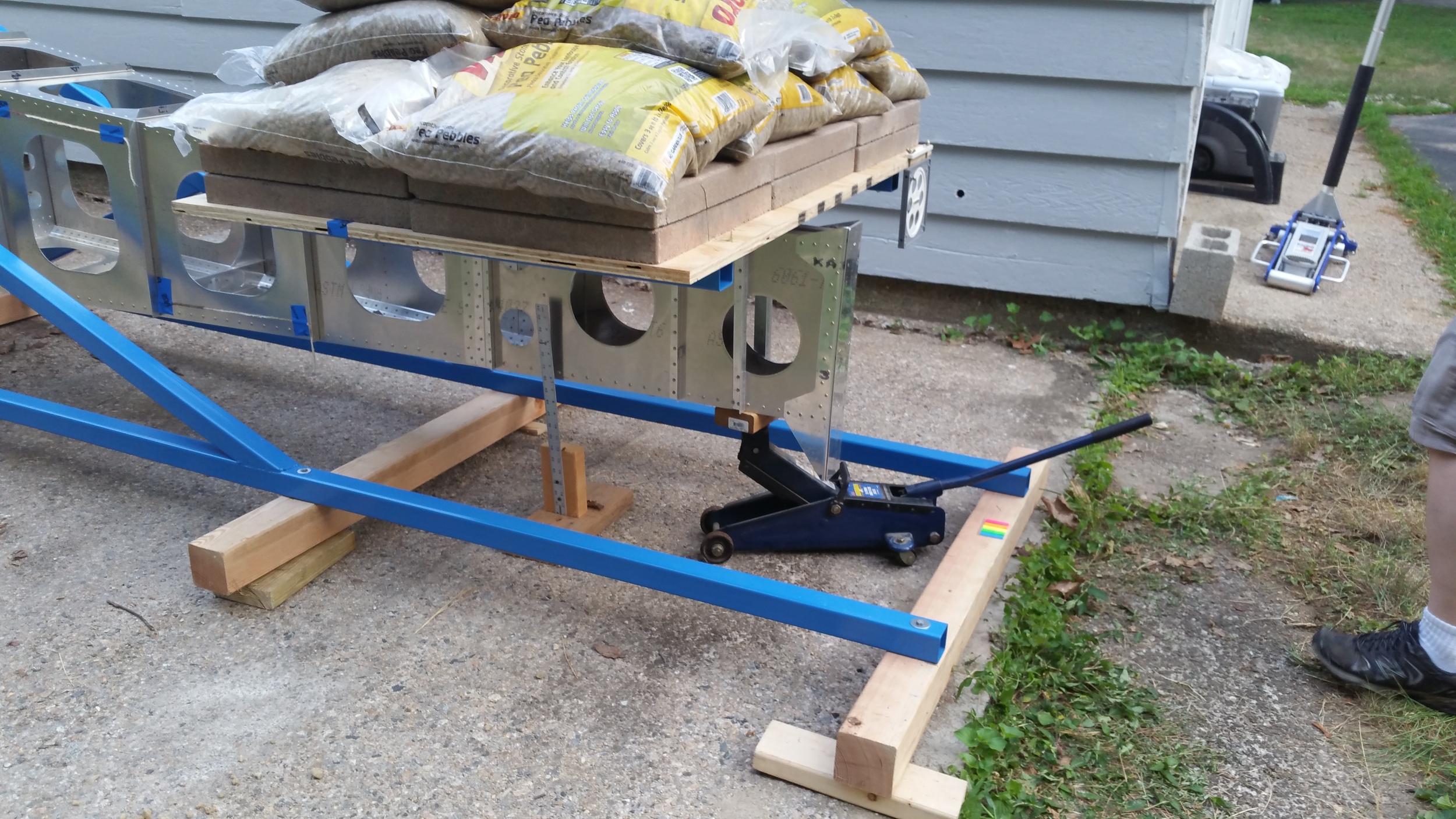
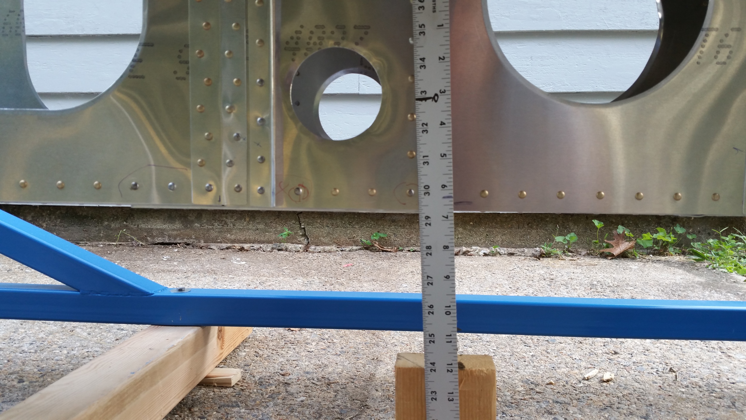
So we thought it over and decided the best way to perform the test was to load the frame in 100 pound increments and see how it did. The test was a very simple cantilever load setup, fixed at one end and then loaded on the other; similar to what anyone does, using a jack under the tail end as we loaded and then removing it to see how much deflection we would get. We measured the height of the tail above the concrete pad and marked our ruler to set the base-line. For each load we waited over 30 seconds for each cycle and then jacked the tail back up to match the baseline before adding more. After your 6G worth of load of 800 pounds, we removed all the weight from the fixture and removed the support. At that point – there was no permanent deflection – zero. Perfect! We then loaded it back to 800 and then proceeded incrementally to 1200 pounds – 9 G’s. Then we removed the loads and support again to check for permanent deflection. This time she took a permanent set, but only 3/8”. After this it was pointed out we also need an asymmetric load test – simulating rudder deflections and air-pocket/turbulence, and that at up to 9 G’s because why not? At that load, it settled at approx. one degree of twist and then returned to level after the load was taken off, so nothing to worry about there it seems either. After that we decided to keep adding weight, see if anything started to change dramatically, so we went incrementally again to 1500 pounds – all the weight we had on hand. This is about 11 g’s equivalent, and she survived, with ½” of permanent deflection.
To sum all that up, I feel we succeeded in meeting all our requirements: The frame survived our design load of 6 g’s with no issues. She survived 11 g’s with no damage, just a permanent sag – It will get you home! But more importantly than the specific design we tested was that the available engineering predictions matched surprisingly accurately to the real world. Does this mean that FEA and basic calculations can replace building these test articles in the future? No! Well, not exactly; it does help add a level confidence to our abilities. I’m not the engineer but in many cases you can reasonably say a certain area is easily strong enough without going through a whole testing regimen to verify it; but it’s about having a method that can be followed to get some results that pan out in the real world, which applies to CAM and CNC as much as it does calculating structures and verifying design integrity.
The final takeaway though? We may be a bit too heavy duty. The whole tail frame weighs in at 27 pounds which is right on the mark as designed, but there appears to be room to optimize. Then again, we like rugged airplanes.
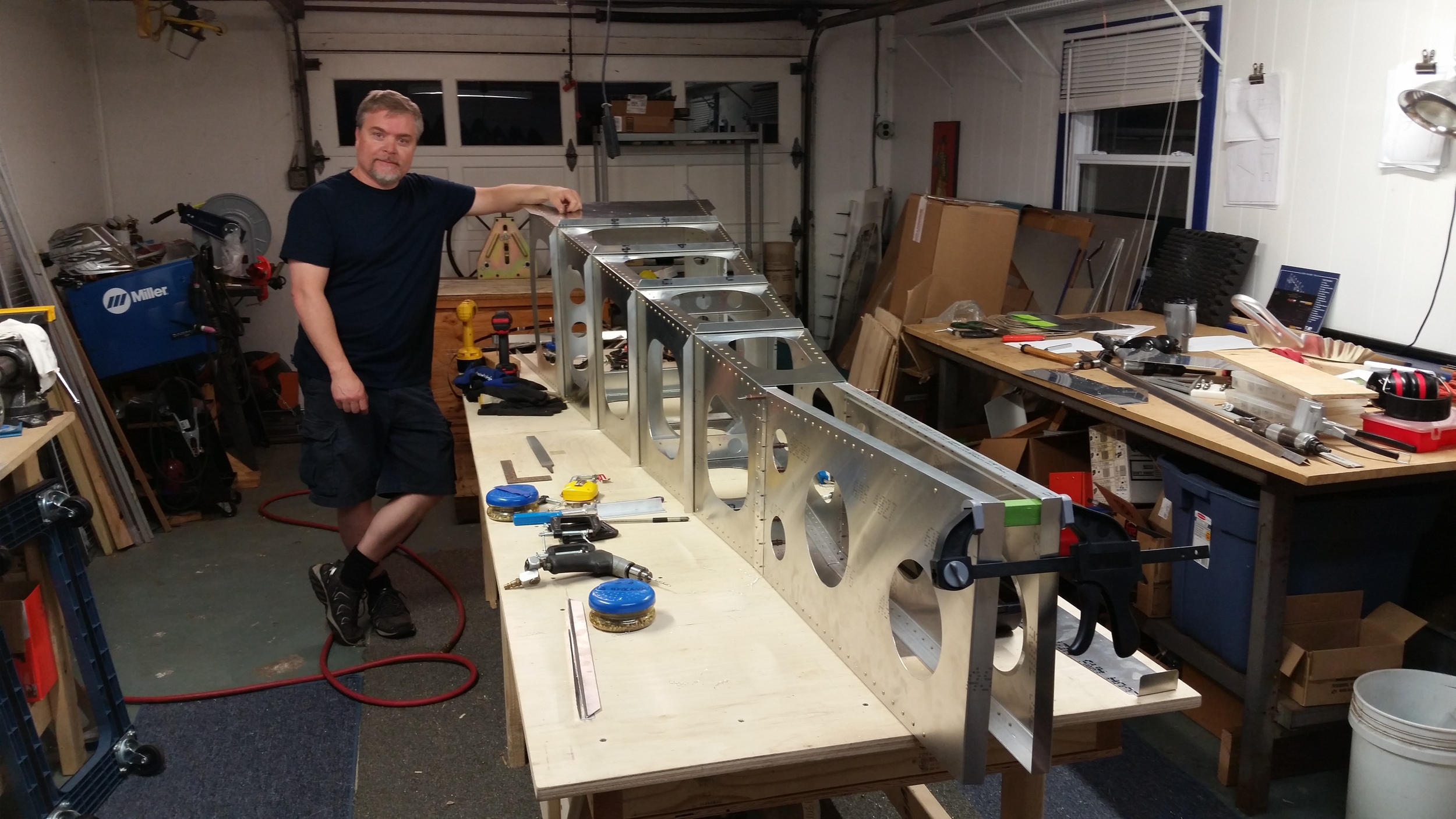
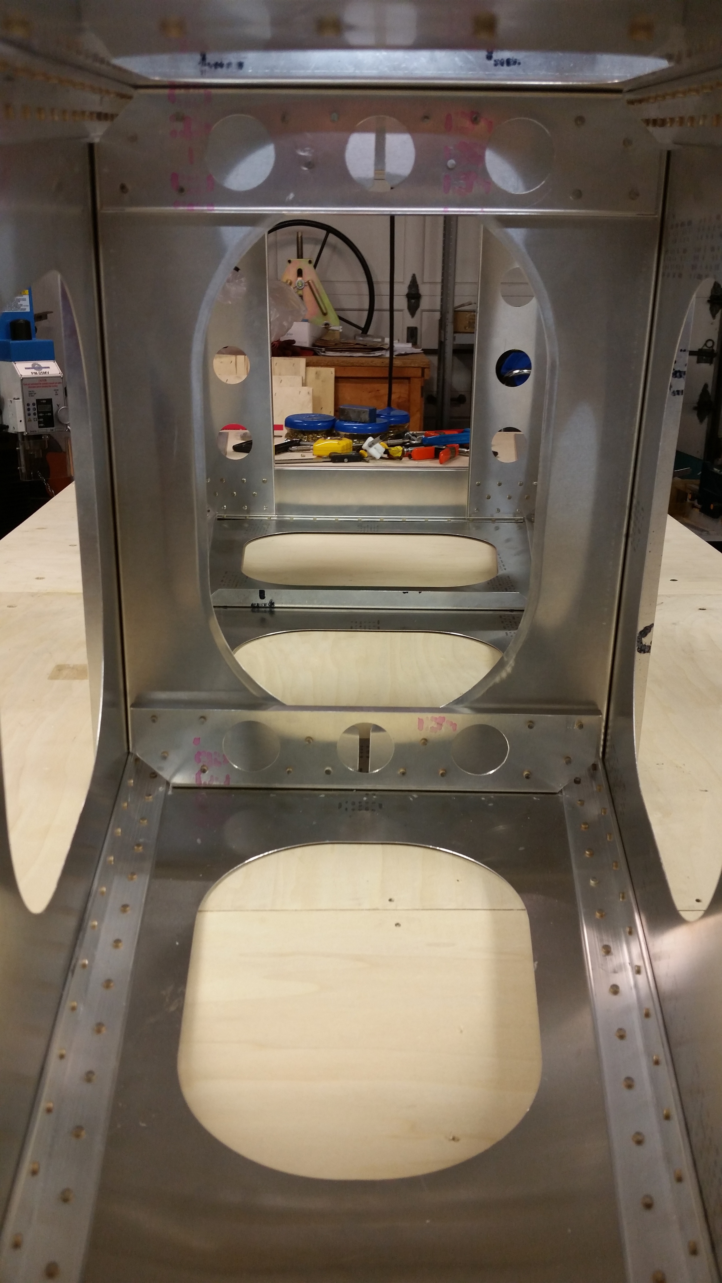
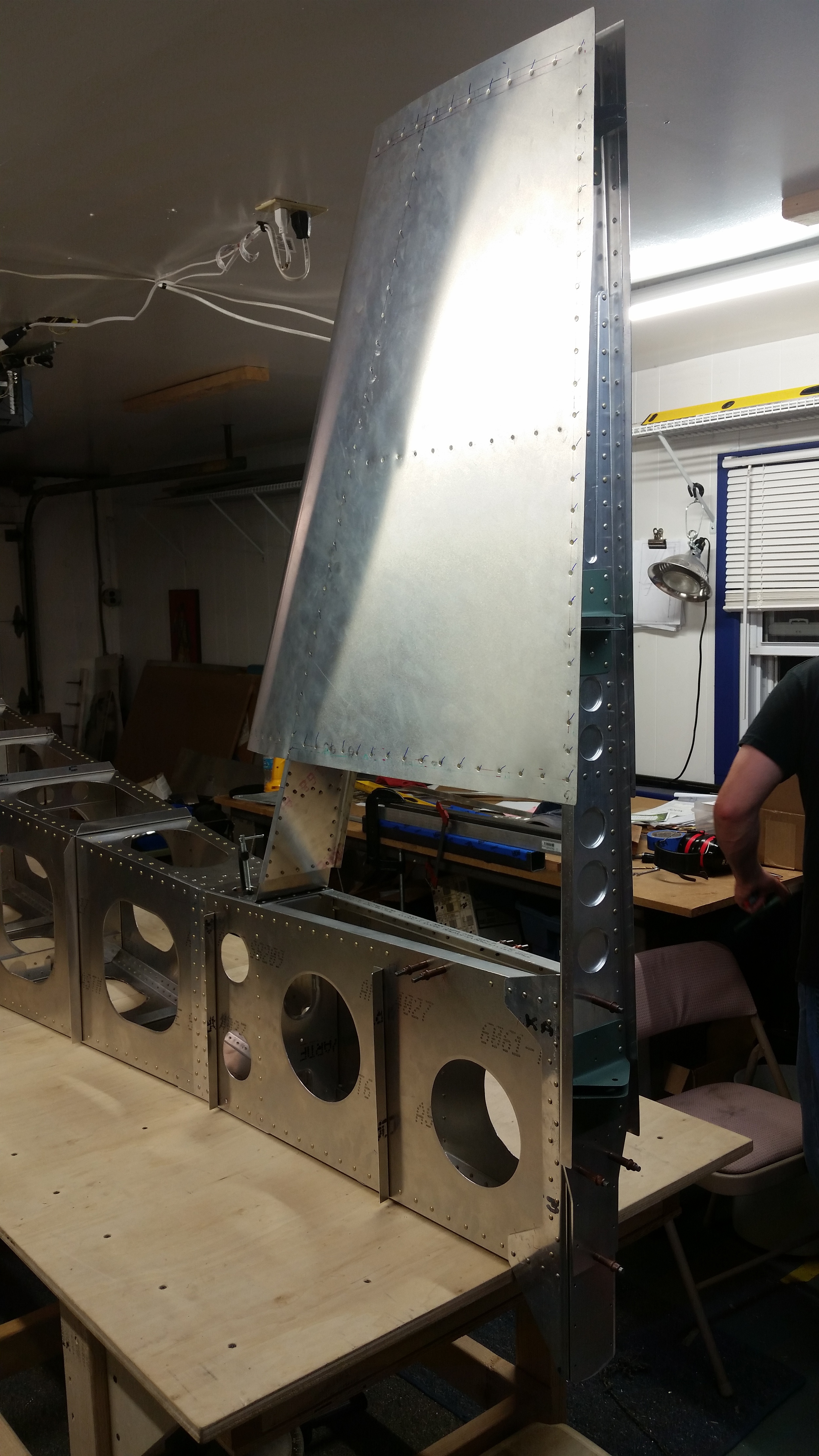
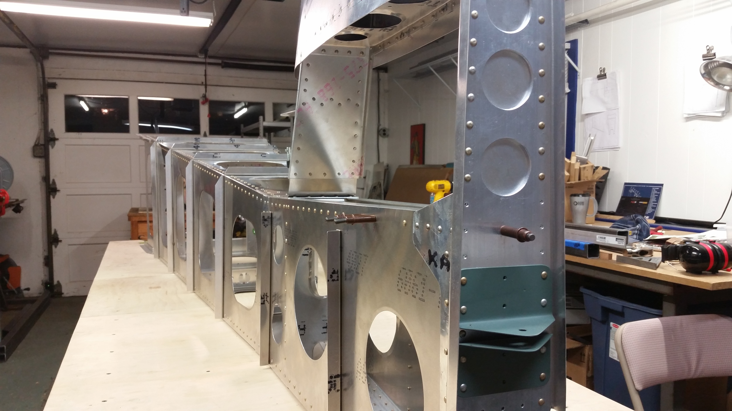
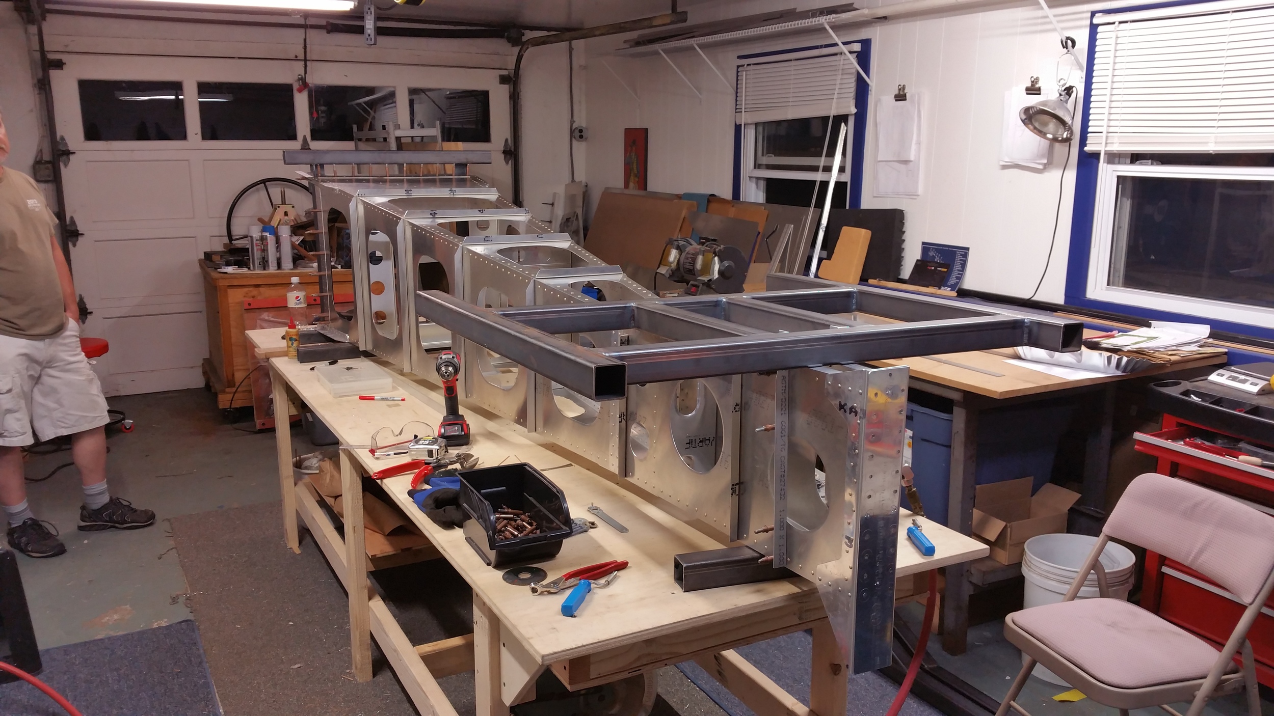
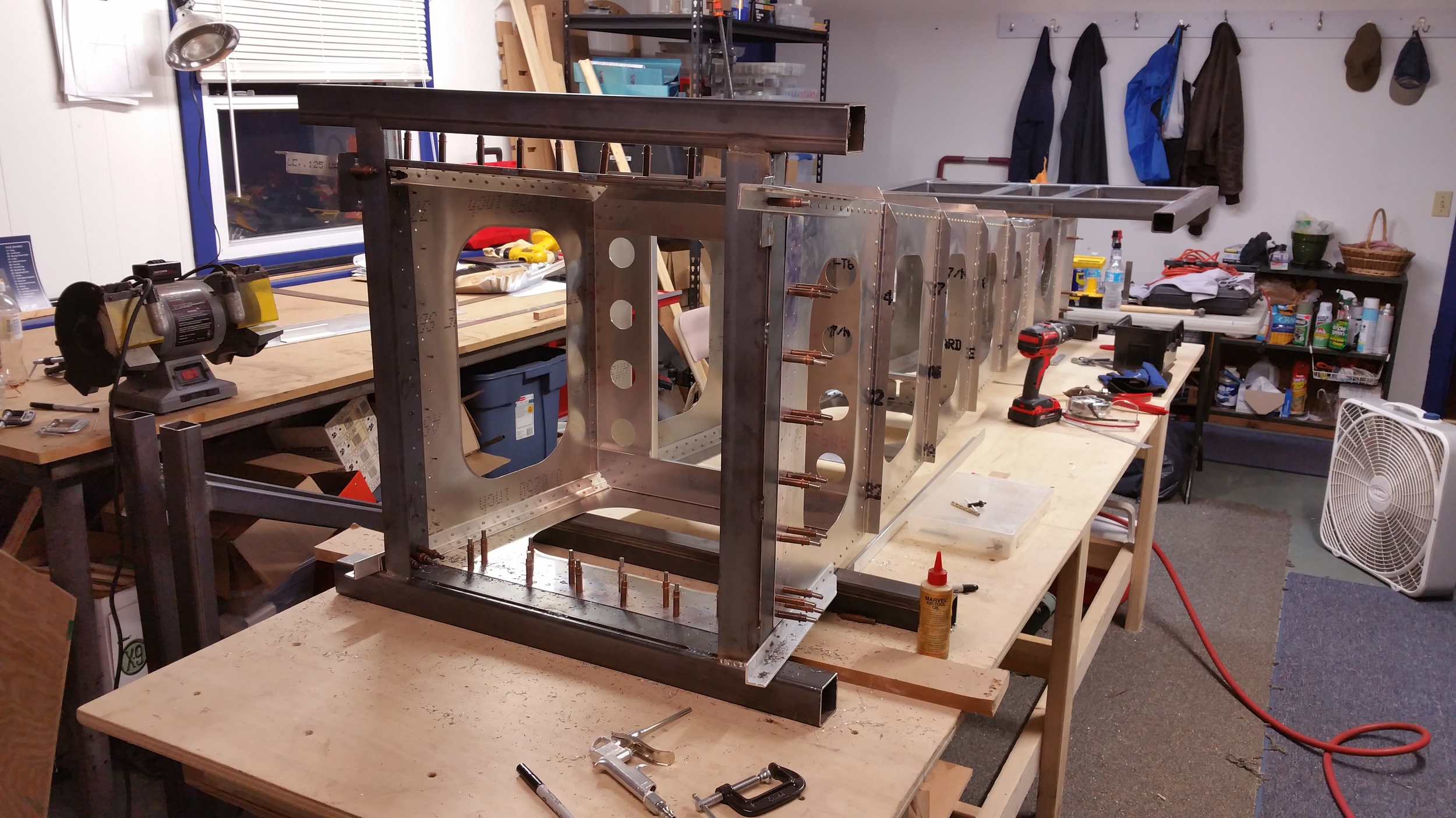
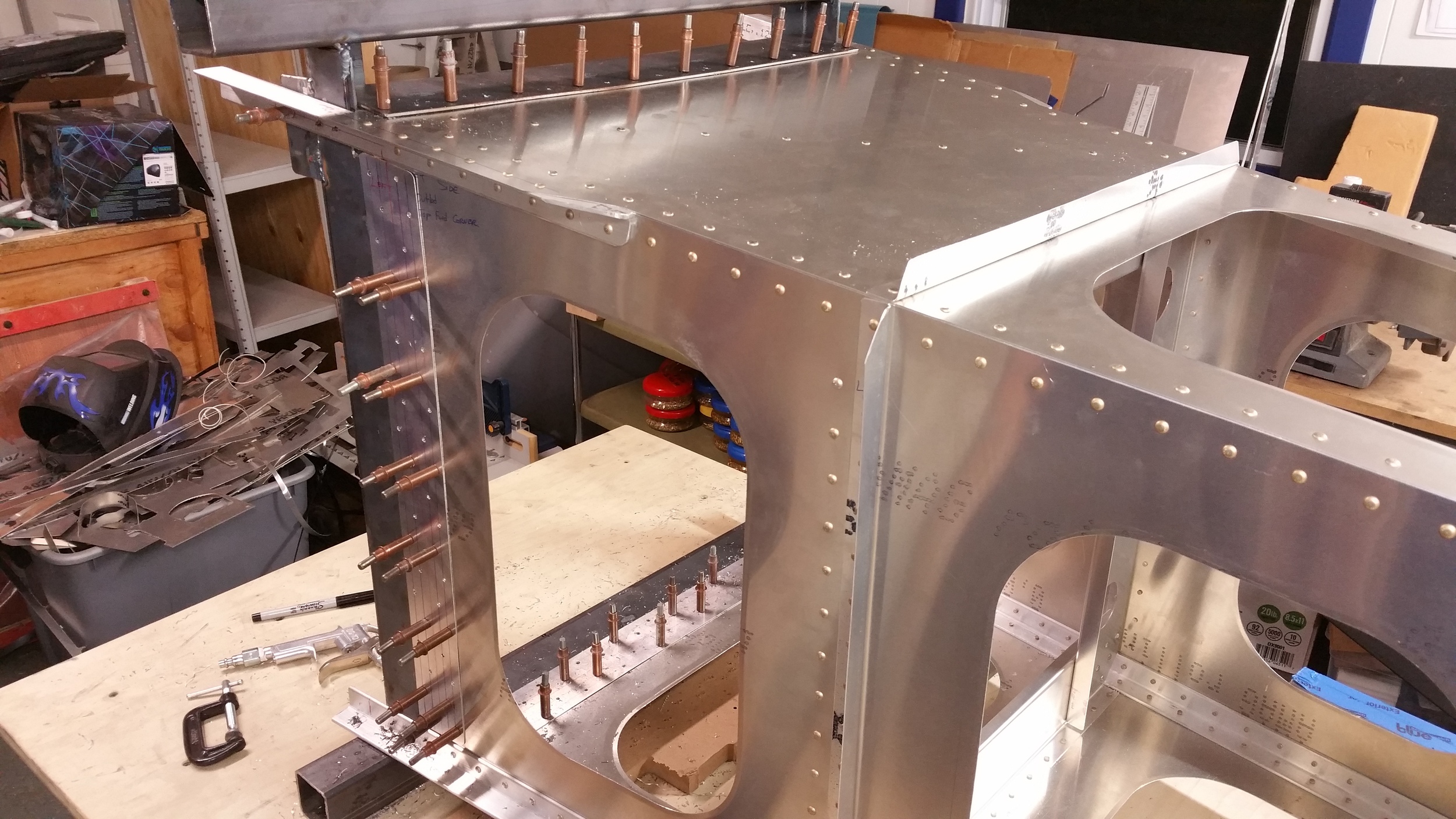
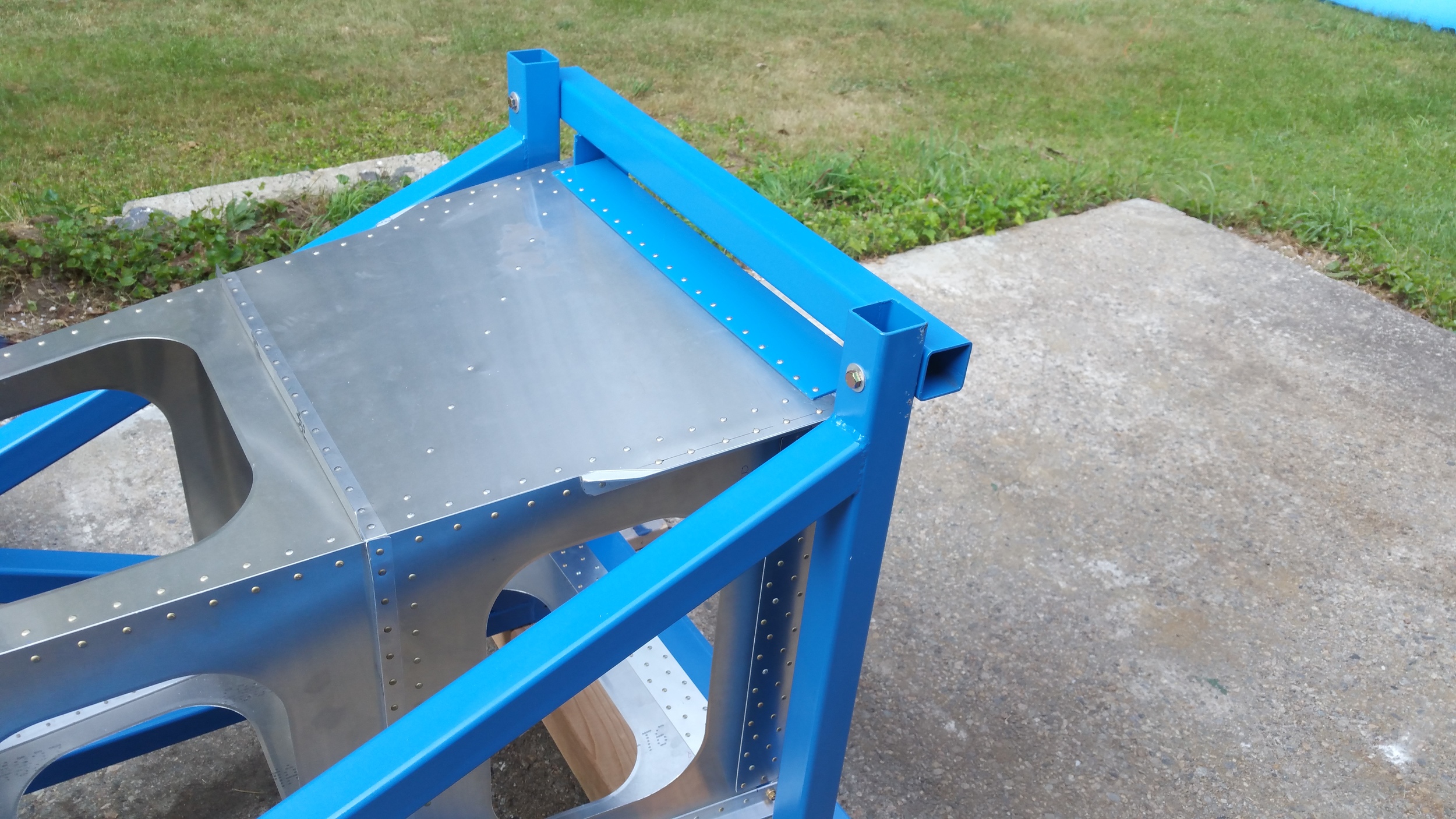
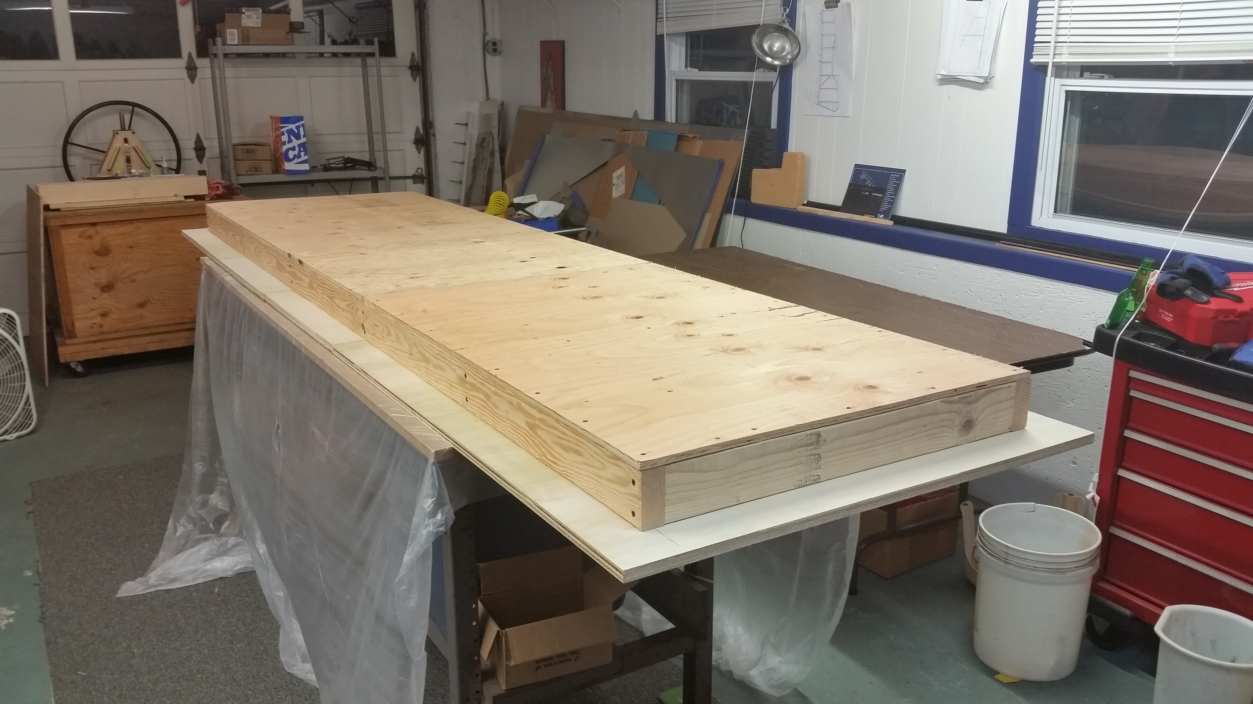
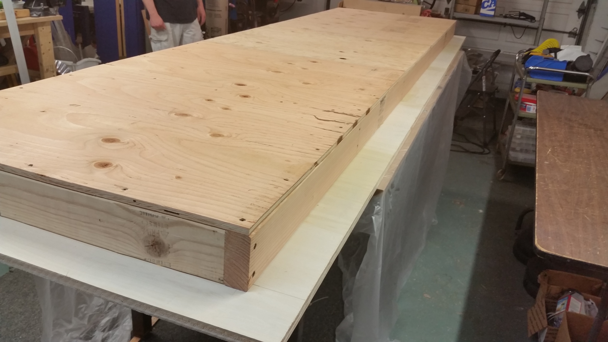
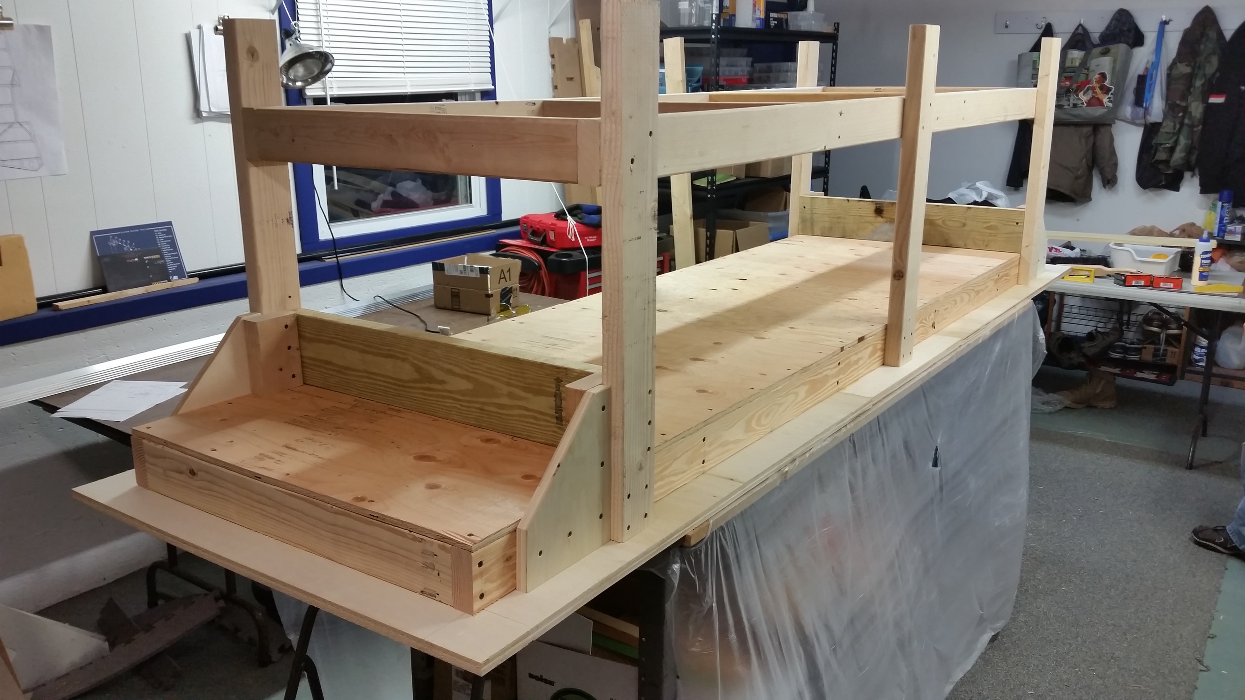
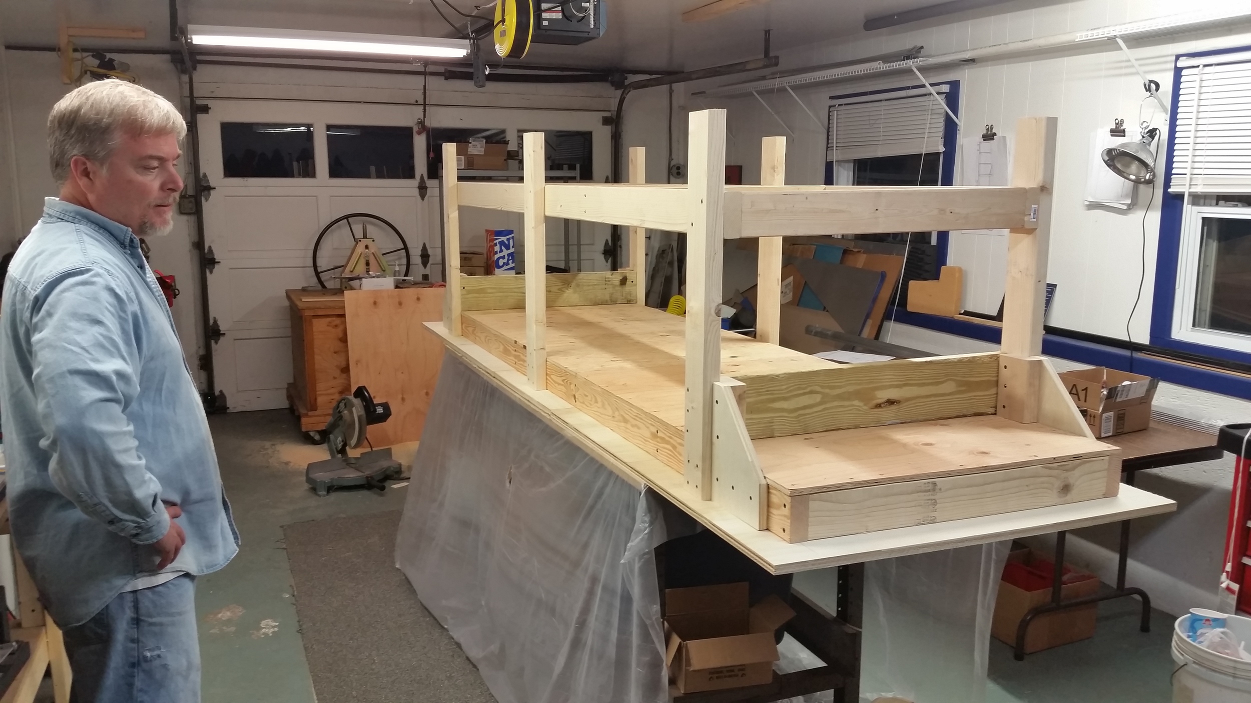
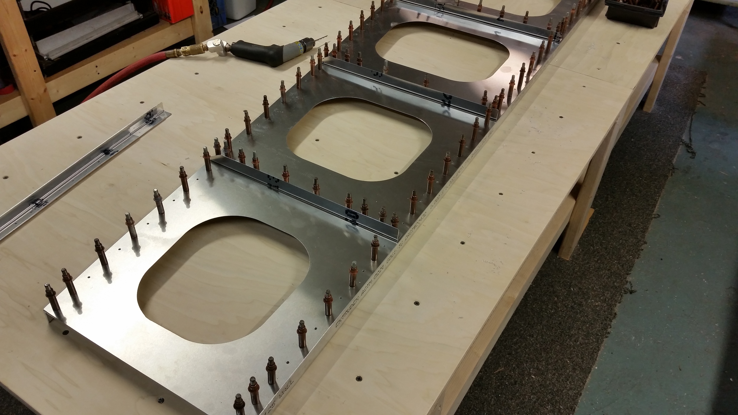
So things have been moving along since finishing the Vertical, we're on to making a box. To elaborate, its a long sturdy box that will be the core of the fuselage frame. This build is specifically for a load test: the piece will be loaded to 9 g’s in increments – just as we did with our horizontal test piece. We are again looking to see how the sample will differ from the calculated expectation, and also whether this design as-is handles the load it will need to in flight, and to what degree over or under that is. I guess they are different aspects of the same problem; in my eye the pragmatic "does it work" viewpoint is the ultimate goal regardless, but having models agreeing to that end seems important. I'm not claiming to be the numbers man.
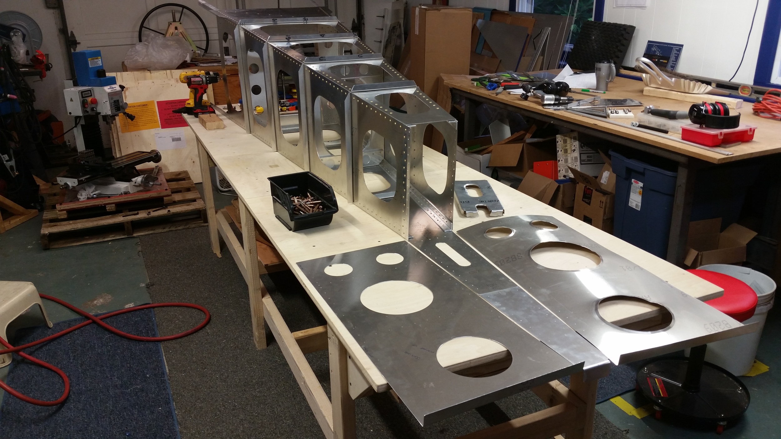
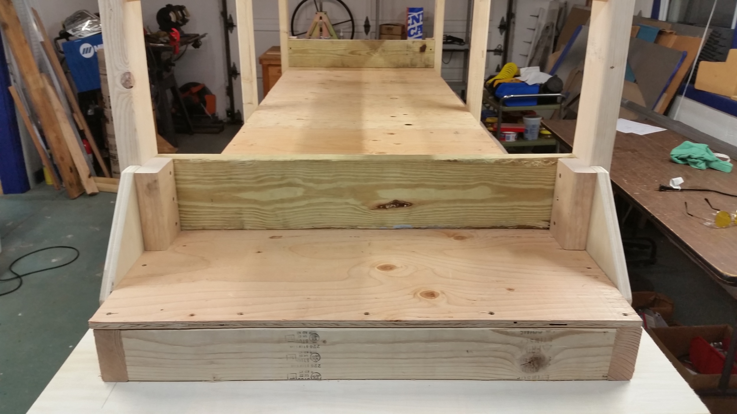
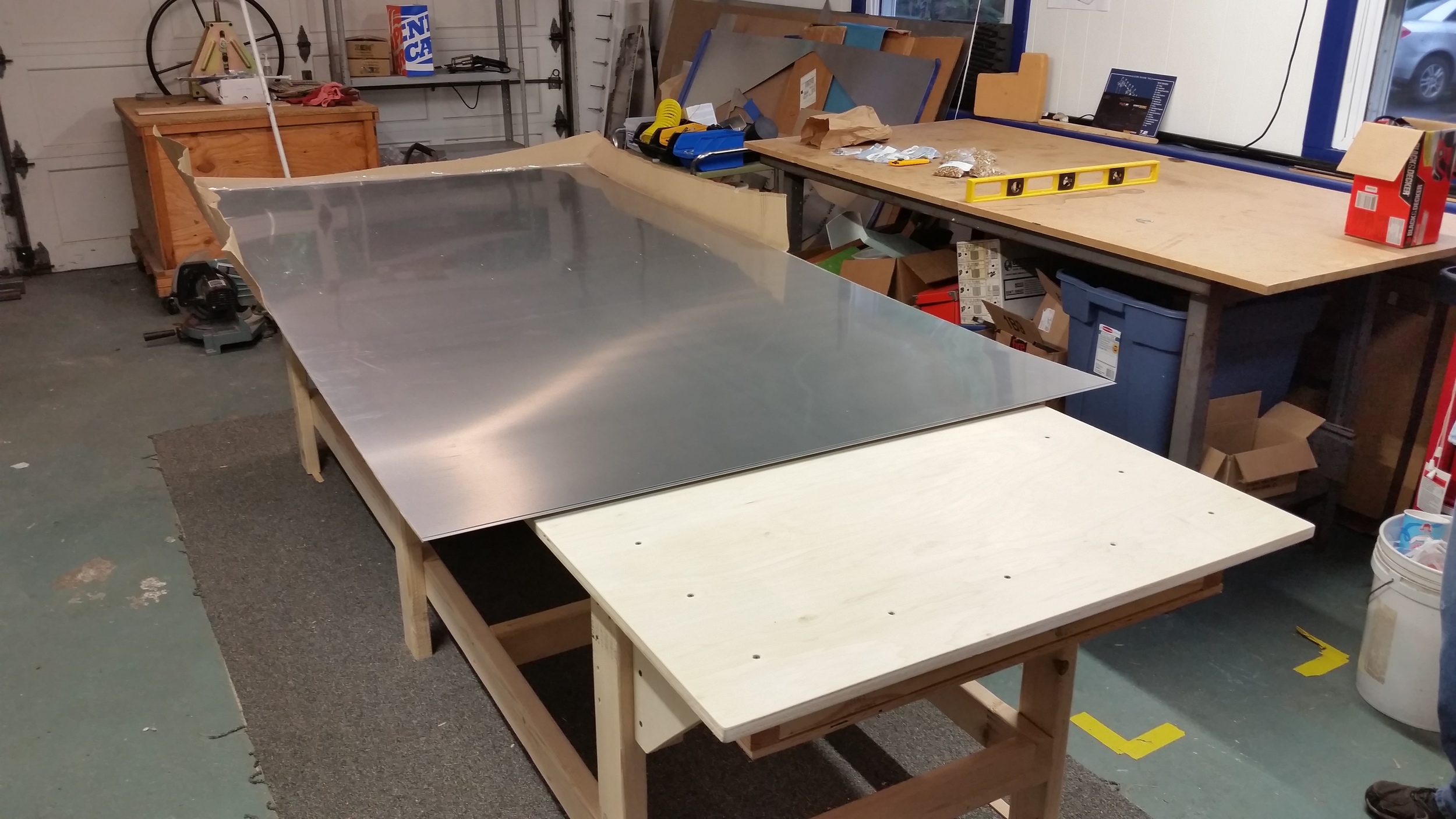
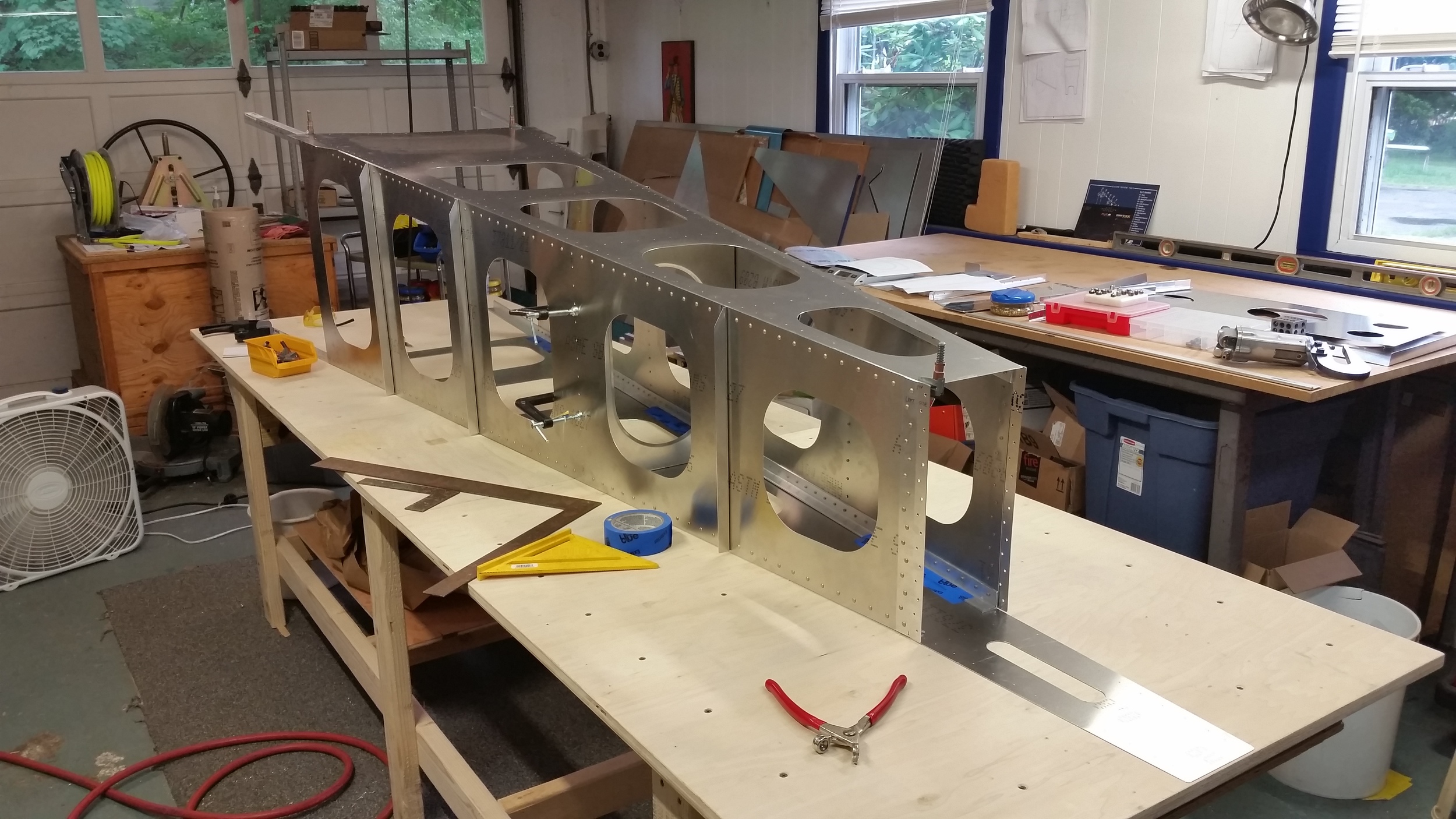
So before we even get into the actual fuselage stuff, I mentioned last update we were building a table from plywood and such. Well, yes, we have a table now. It's not a perfect plane, we diddn't plane every board to within .005 of an inch or anything, but it's about as dead flat as you need for building your aircraft on, easily less than 1/16 deviation over the thing. So here's what that looks like:
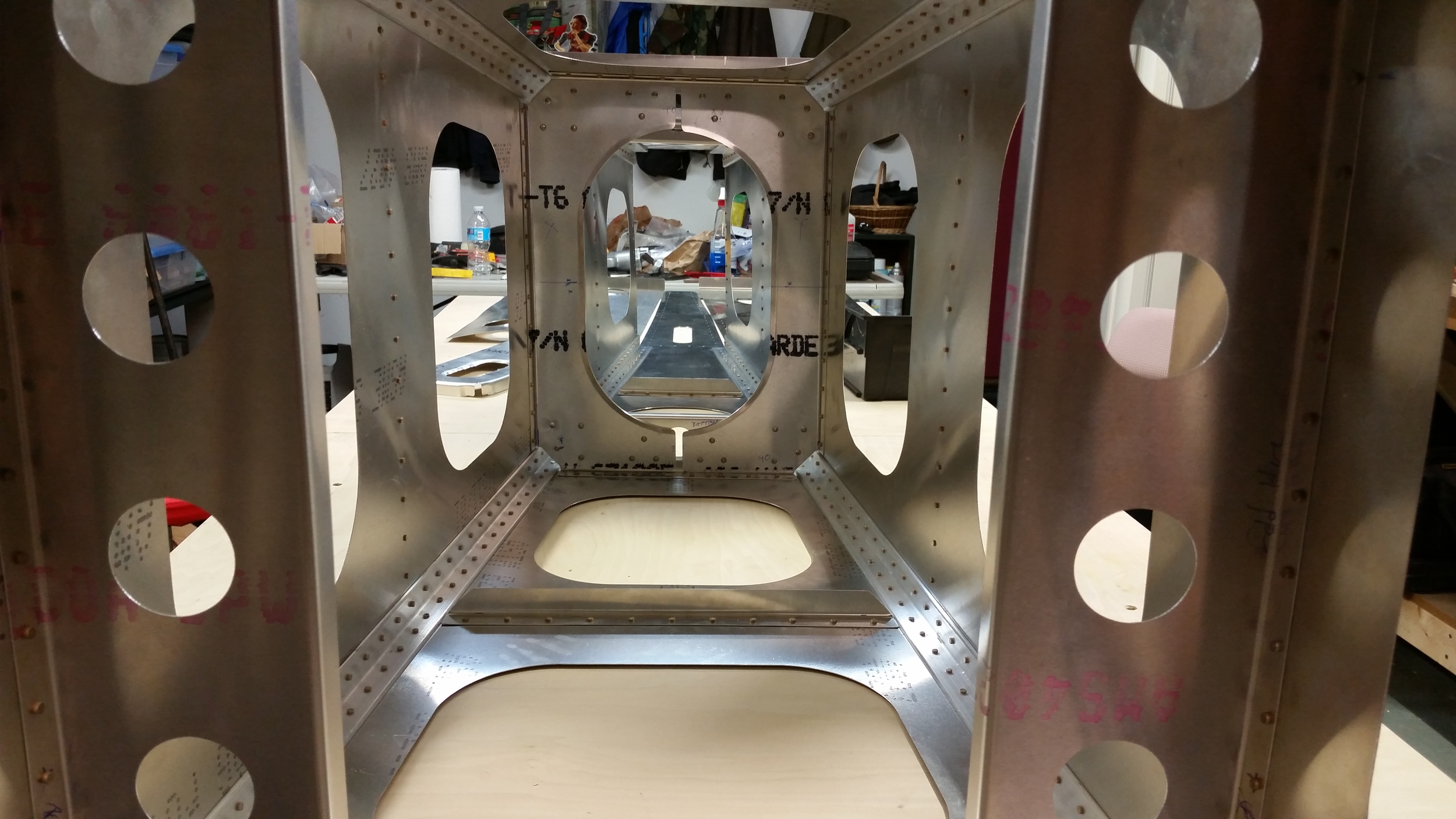
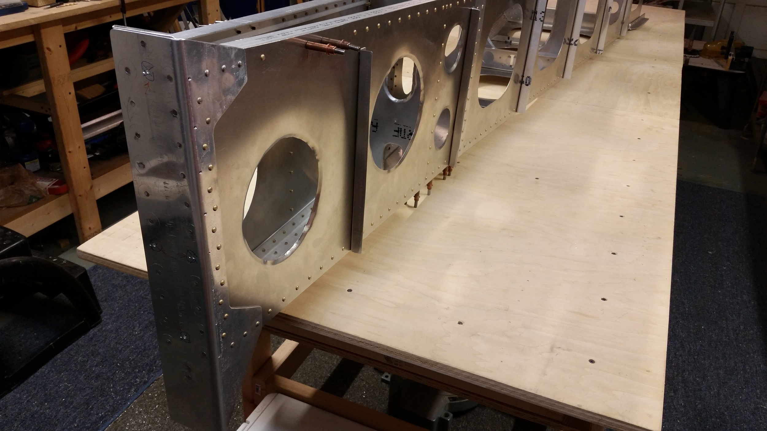
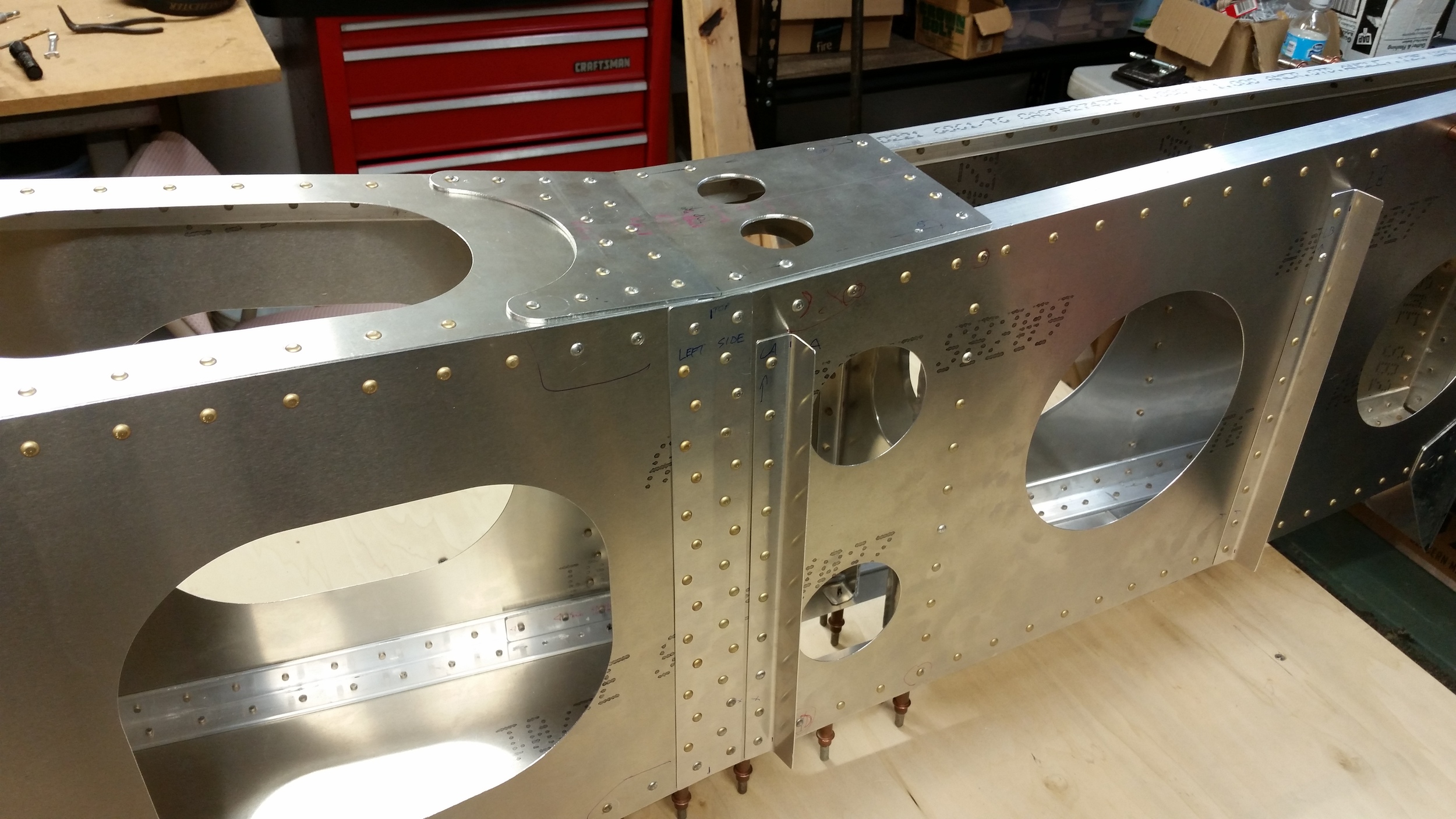
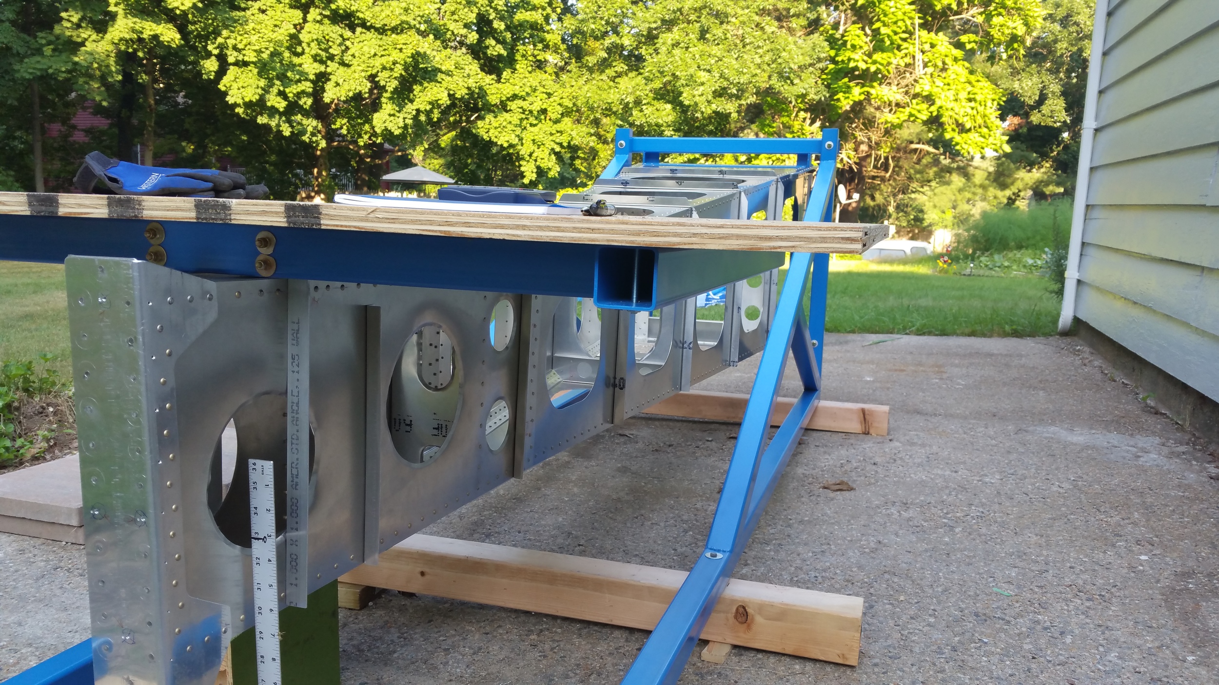
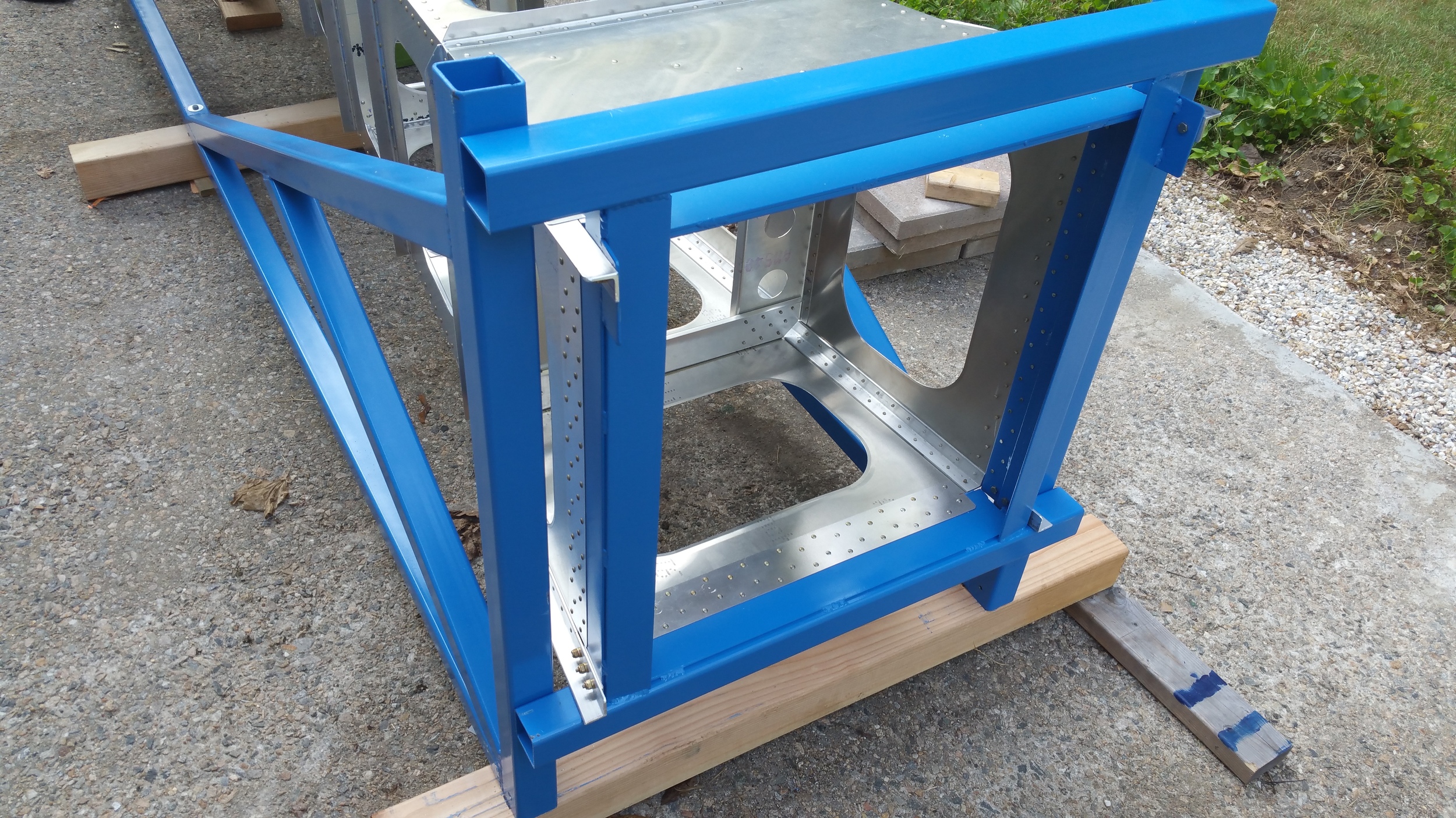
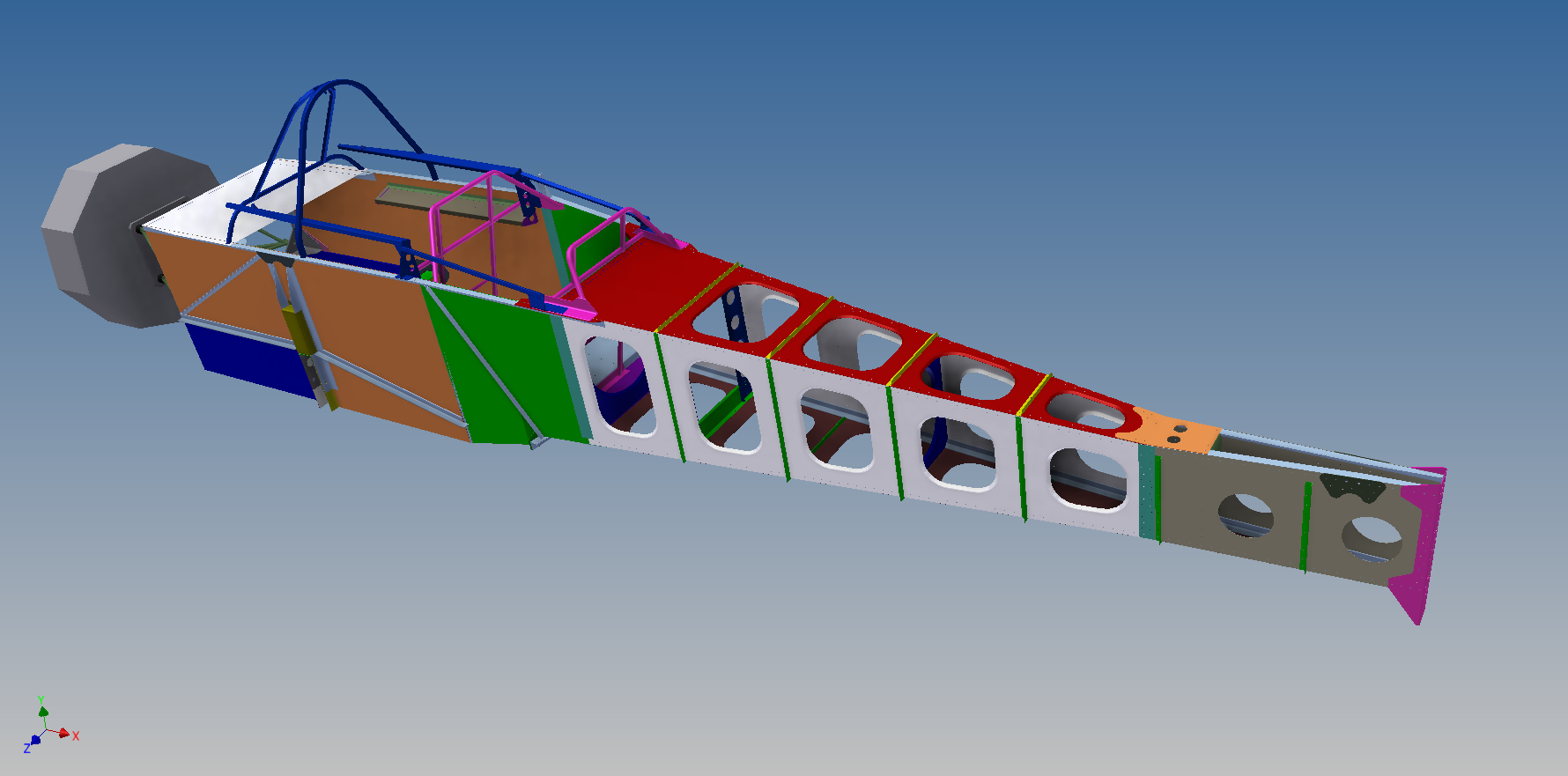
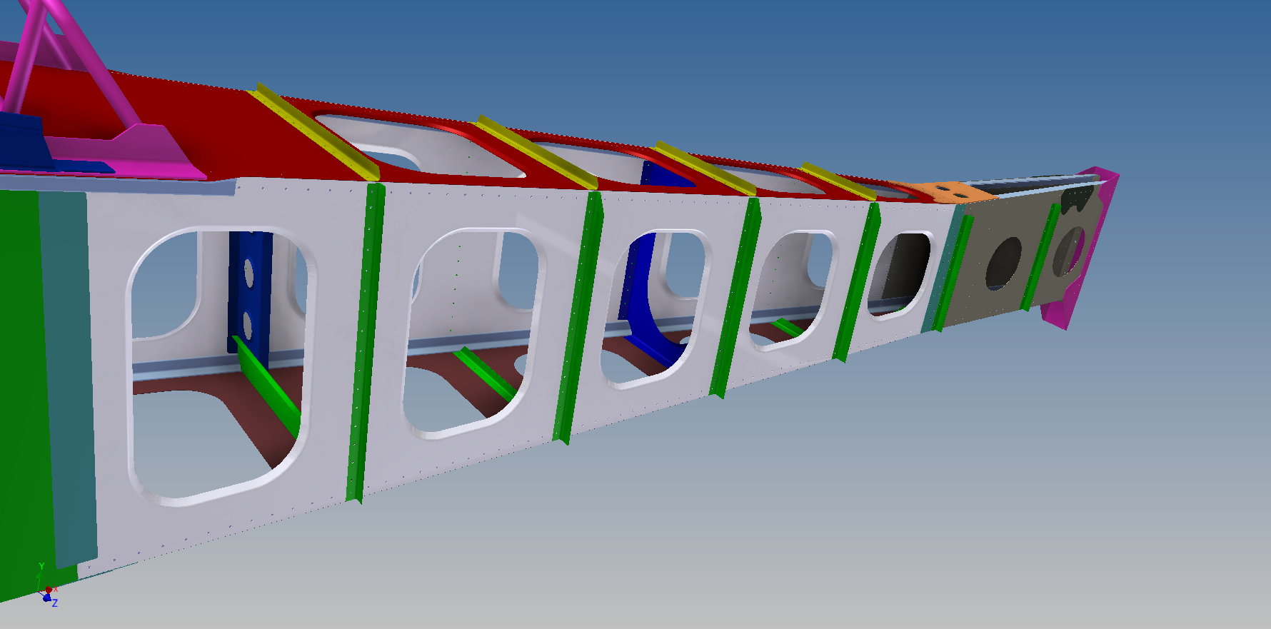
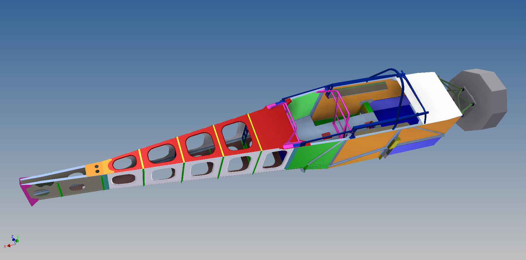
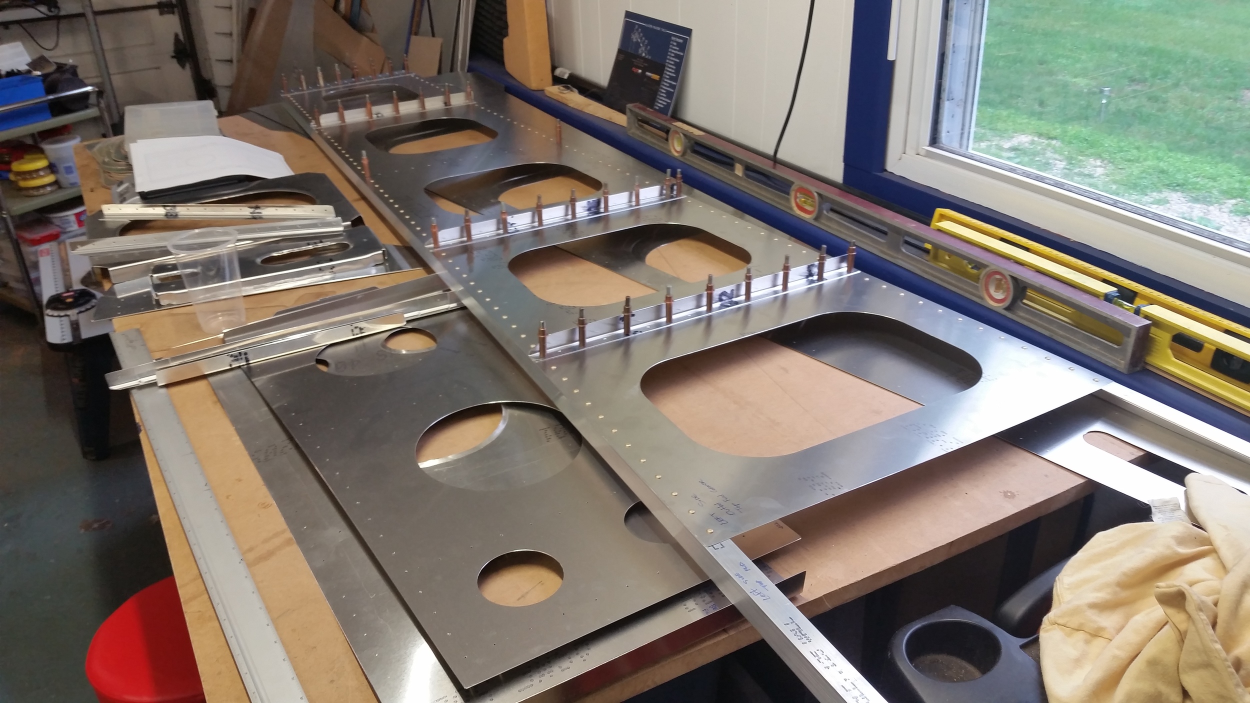
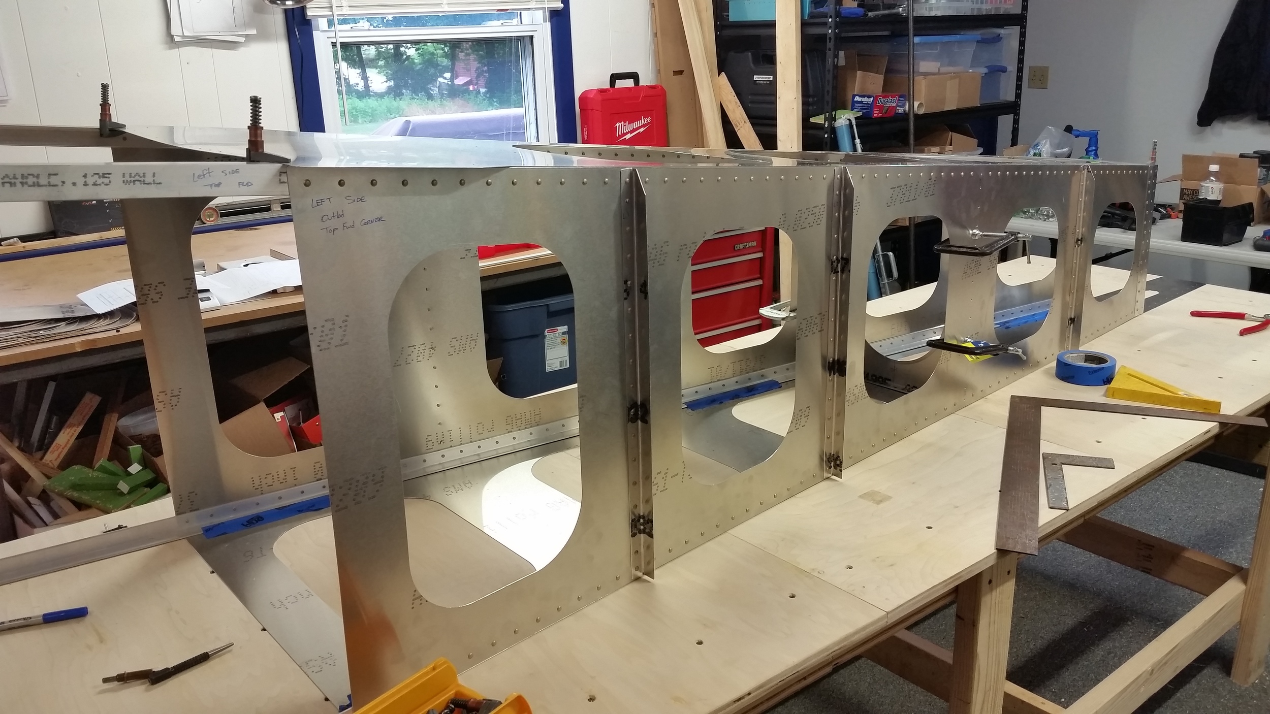
The aft fuselage that we're sampling here, goes from a bulkhead behind the rear seat of our main cockpit box, all the way down to the tail post. The design is very straightforward; 4 longerons made of of L-channel tie together 4 side-sheets to form a long box. Stiffeners and a few bulkheads are evenly spaced along the length to tie everything together, prevent buckling or twisting, and in the final full fuselage built the stiffeners actually act as attachment brackets for the outer skin bulkheads and stiffeners. Those will inevitably add extra support but the hope of the design is to make this box self-sufficient for the intended loads, and give us the flexibility to hang any type of outer shapes we wish. That's the whole objective here of ScaleBirds anyway right? Make it easy to go wild later.
For the build, I had to first generate good CAD data. I had a design in 3D already, but I had to further detail the aft part of the fuselage design in Inventor from where it was originally, mainly adding holes and details wherever it was needed. It took a while and I feel like the master-modelling method I'm using on the fuselage is reaching the limits of practicality; I started seeing crashes and long-long delays to update the feature tree after a change. At some point, I'll probably be having to go in and re-model the entire frame from smaller files once we have dimensions we like. The ideal would be to break it down to where each panel and part of metal gets its own part file, but it makes for a convoluted assembly where everything has to be interlocked anyway, so I figured doing it all in-situ in a single part file would give me greater flexibility while fleshing out the design and avoiding over-use of problematic reference dimensions. The good news is that unlike all the aerodynamic surfaces I've been having to deal with lately, I can directly model everything and export it to 2D as its all flat and I don't have to worry about curved-surface distortions and such. This means when I output the files into 2D I get true geometry that can be cut.
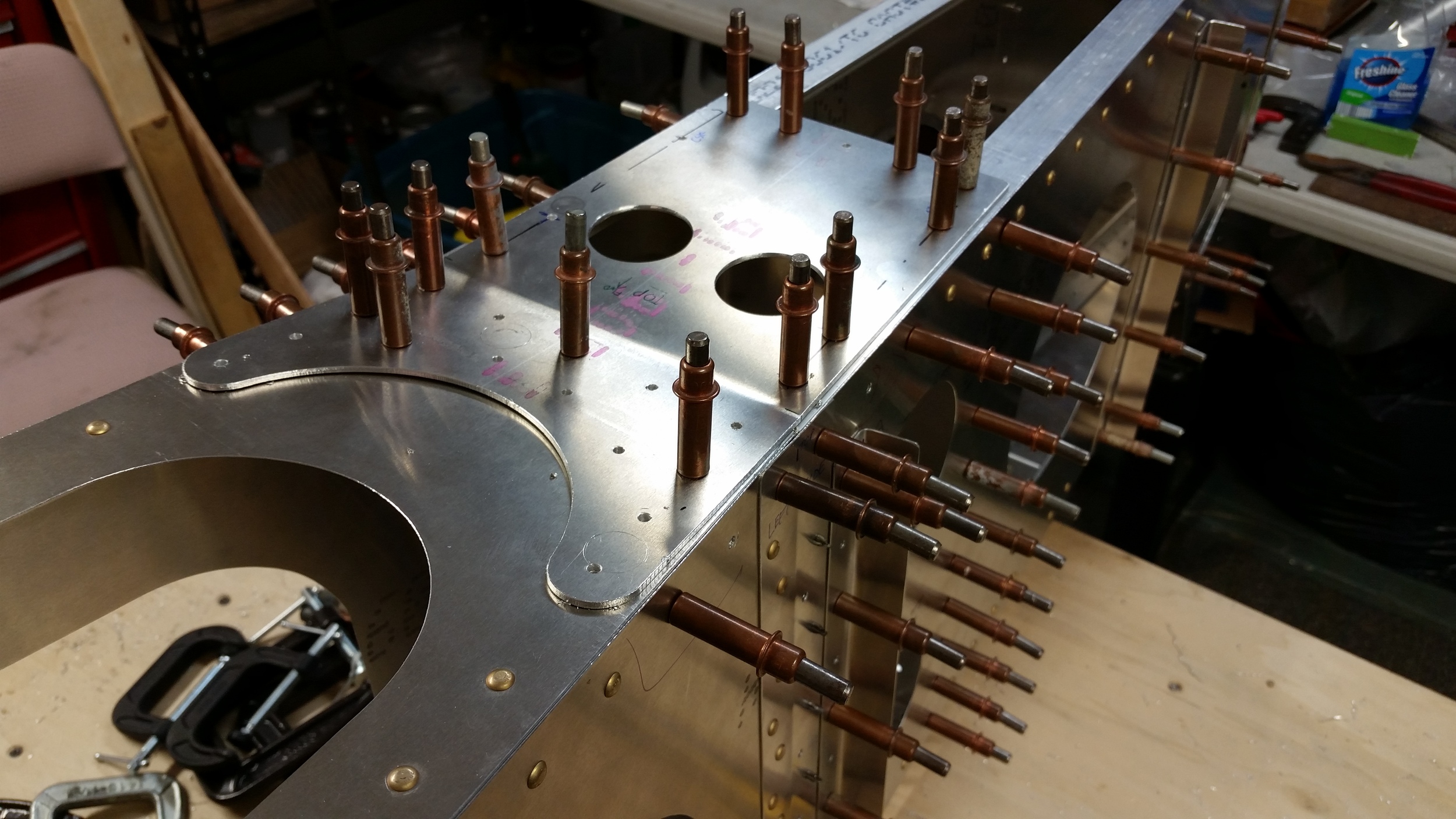
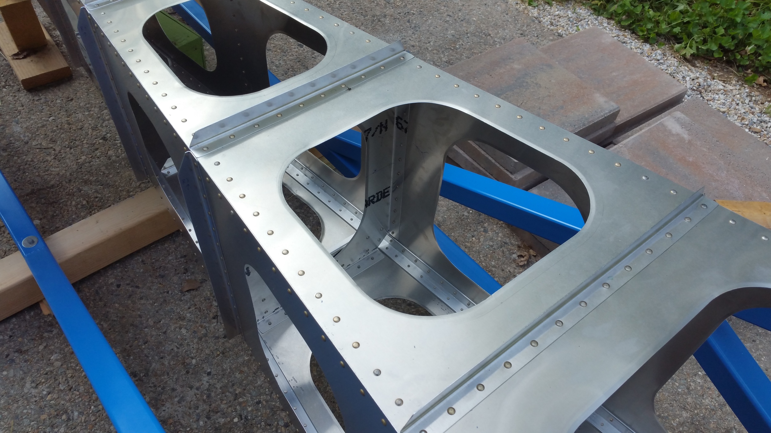
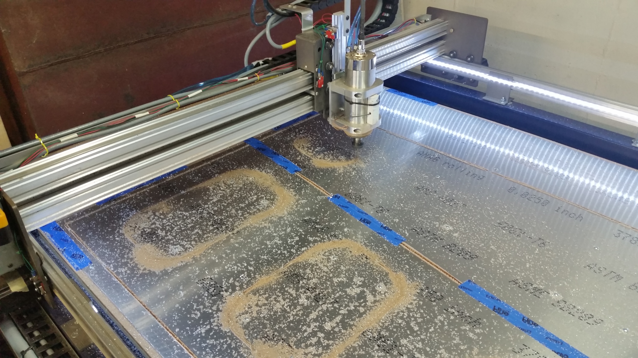
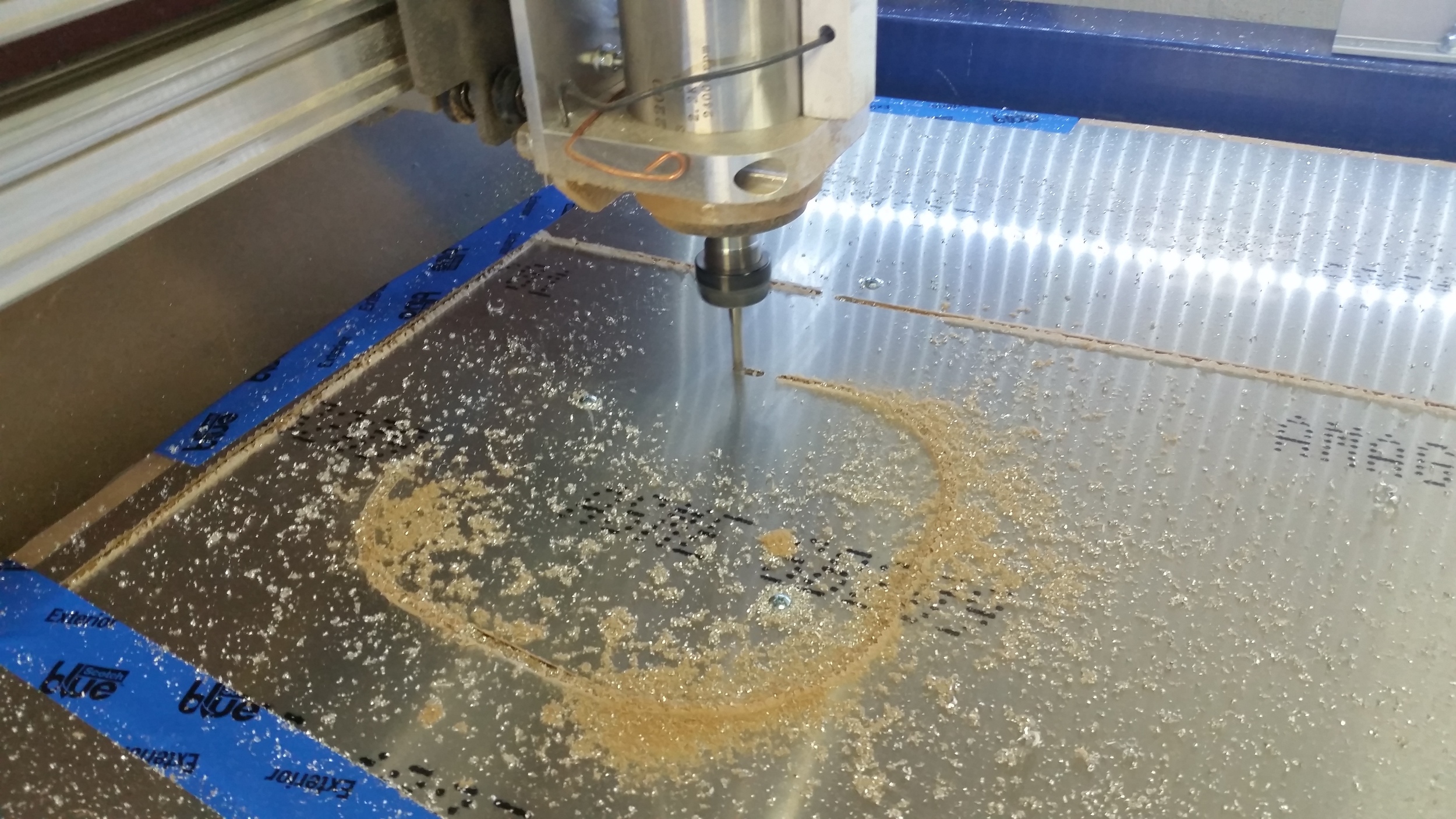
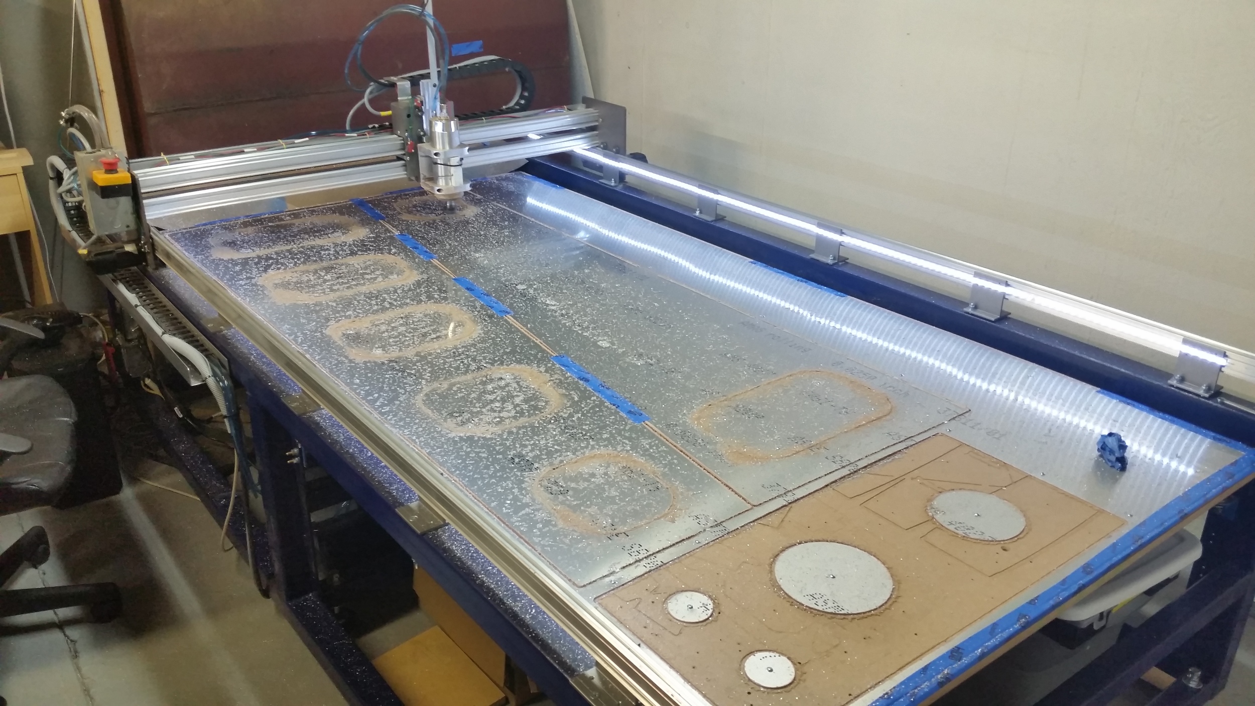
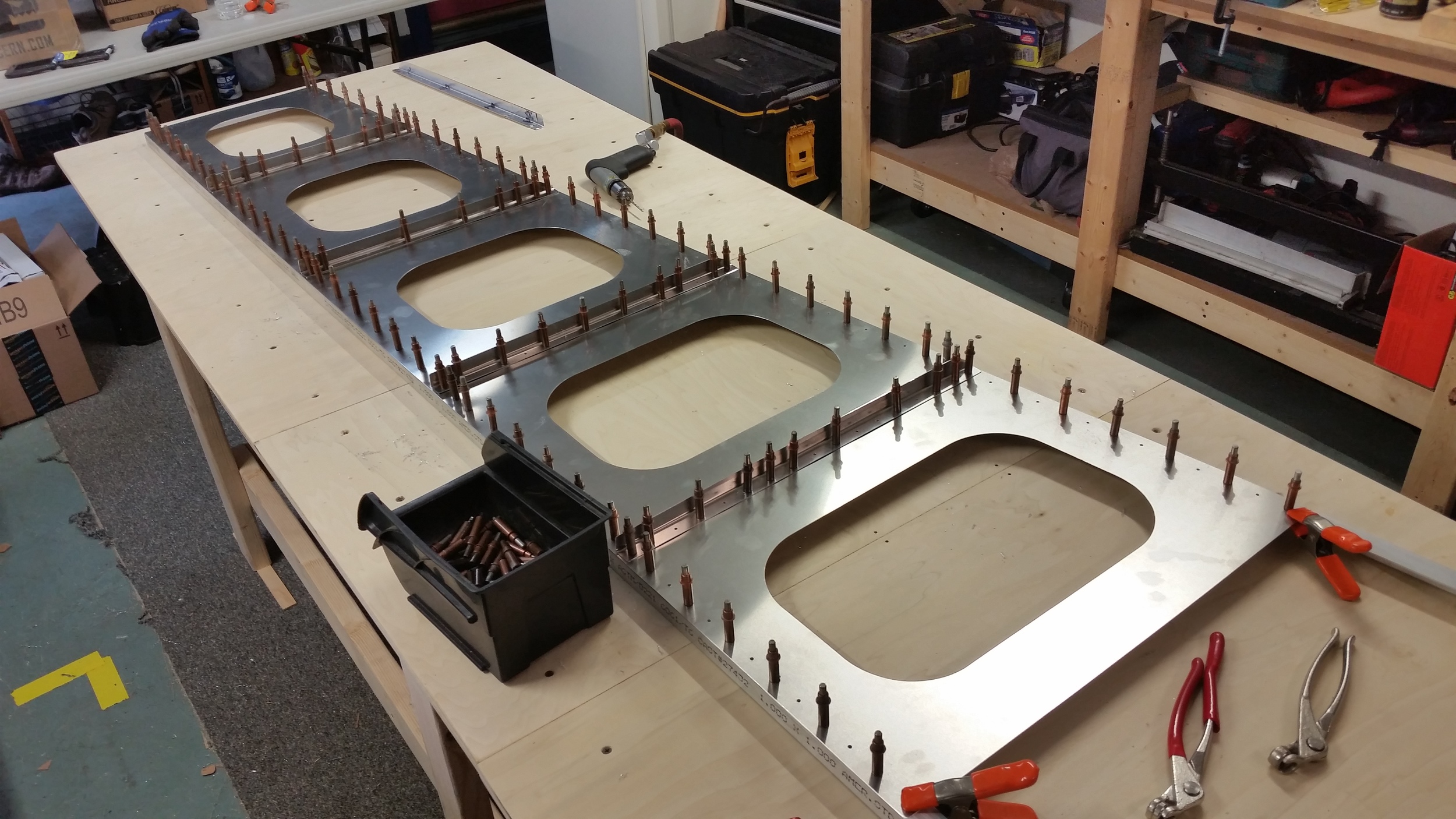
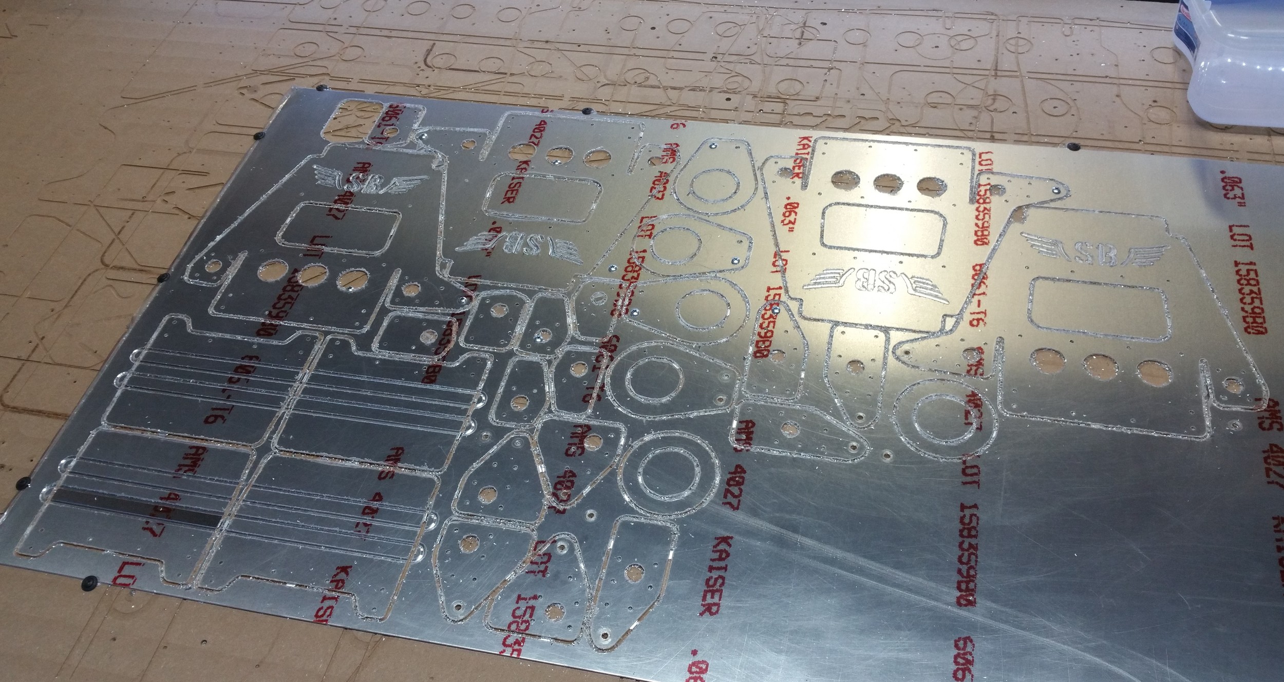
So it came to cutting out parts. I rigged up the patterns into CUT2D, and proceeded to cut the main panels from a pair .025 sheets. (The aluminum sheet we ordered from Aircraft Spruce, and chose to get it rolled for shipping which cut the delivery cost by a significant amount. I wasn't able to find much of any reference to ordering aluminum in this manner online, so we just took a gamble that the resulting sheet would unwrap flat. Turns out it does, it springs right back to flat condition as if nothing happened.)
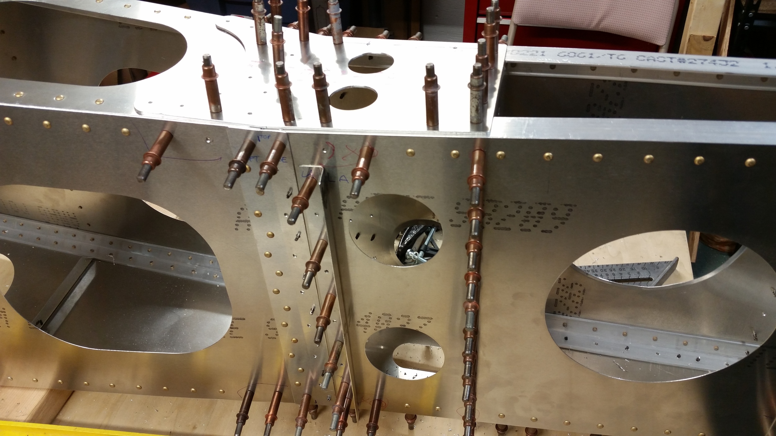
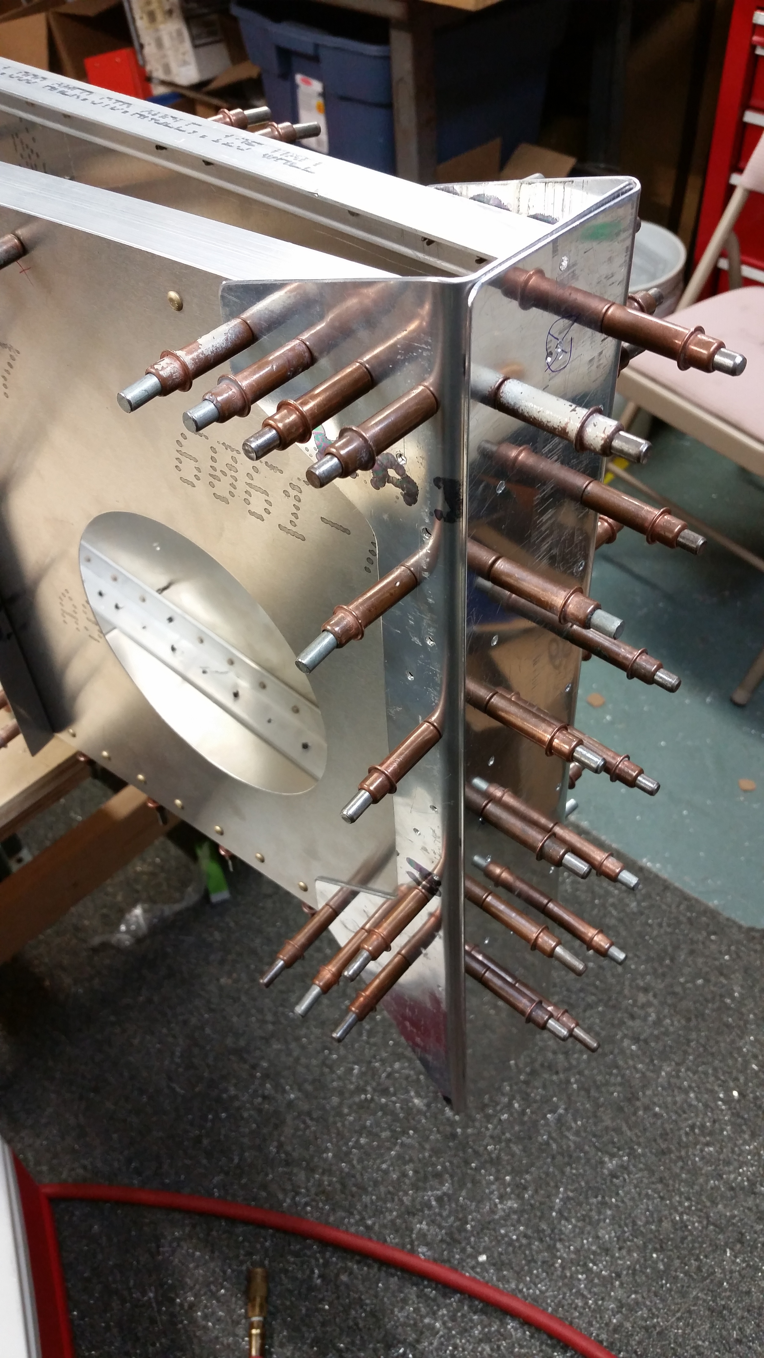
So, Then we set to making some smaller parts that are made of thicker materials, flanges, doublers, etc. Some stuff is left to cut still, where we had to order more materials; but either way, the parts we did do came out looking great.
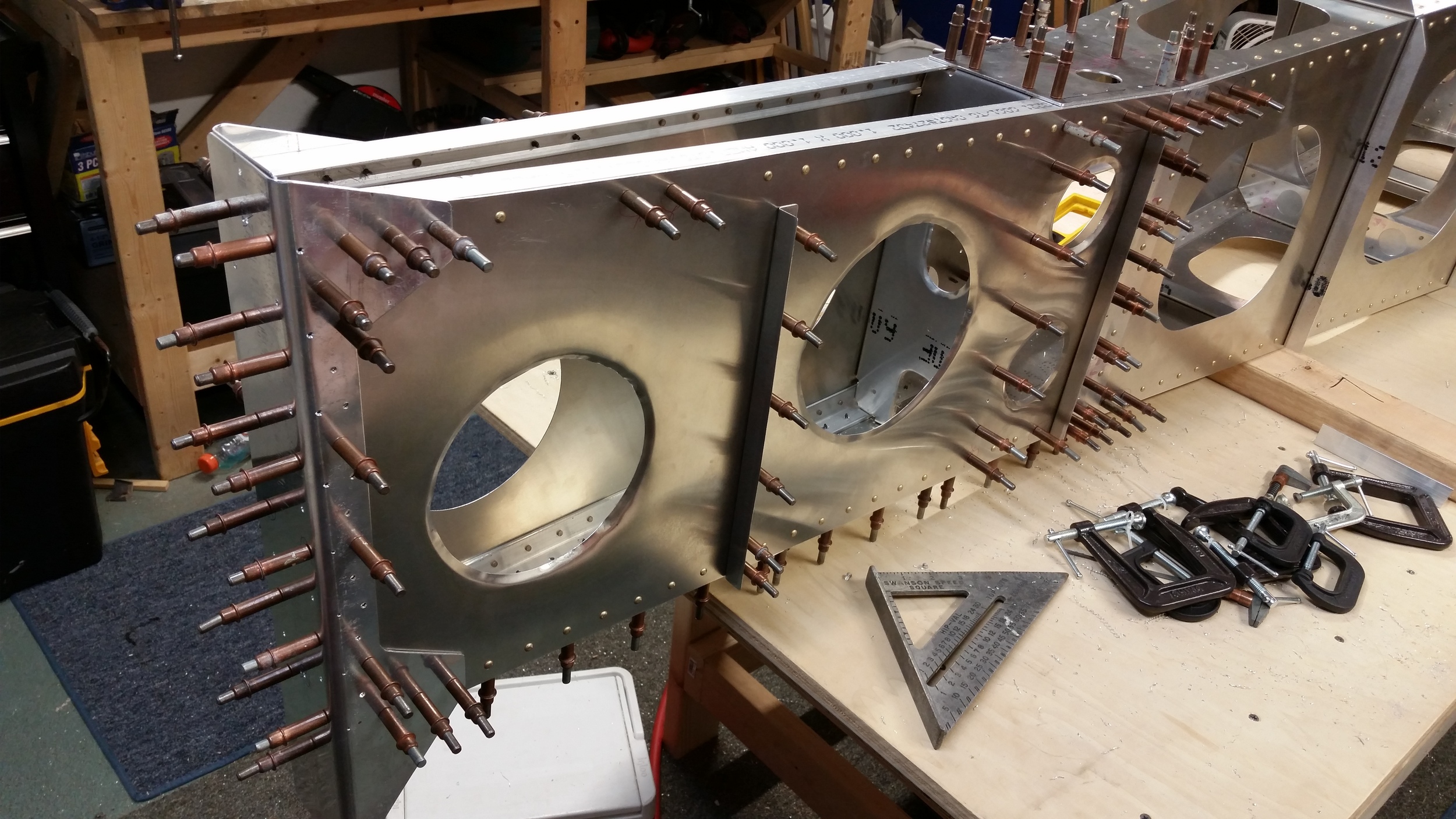
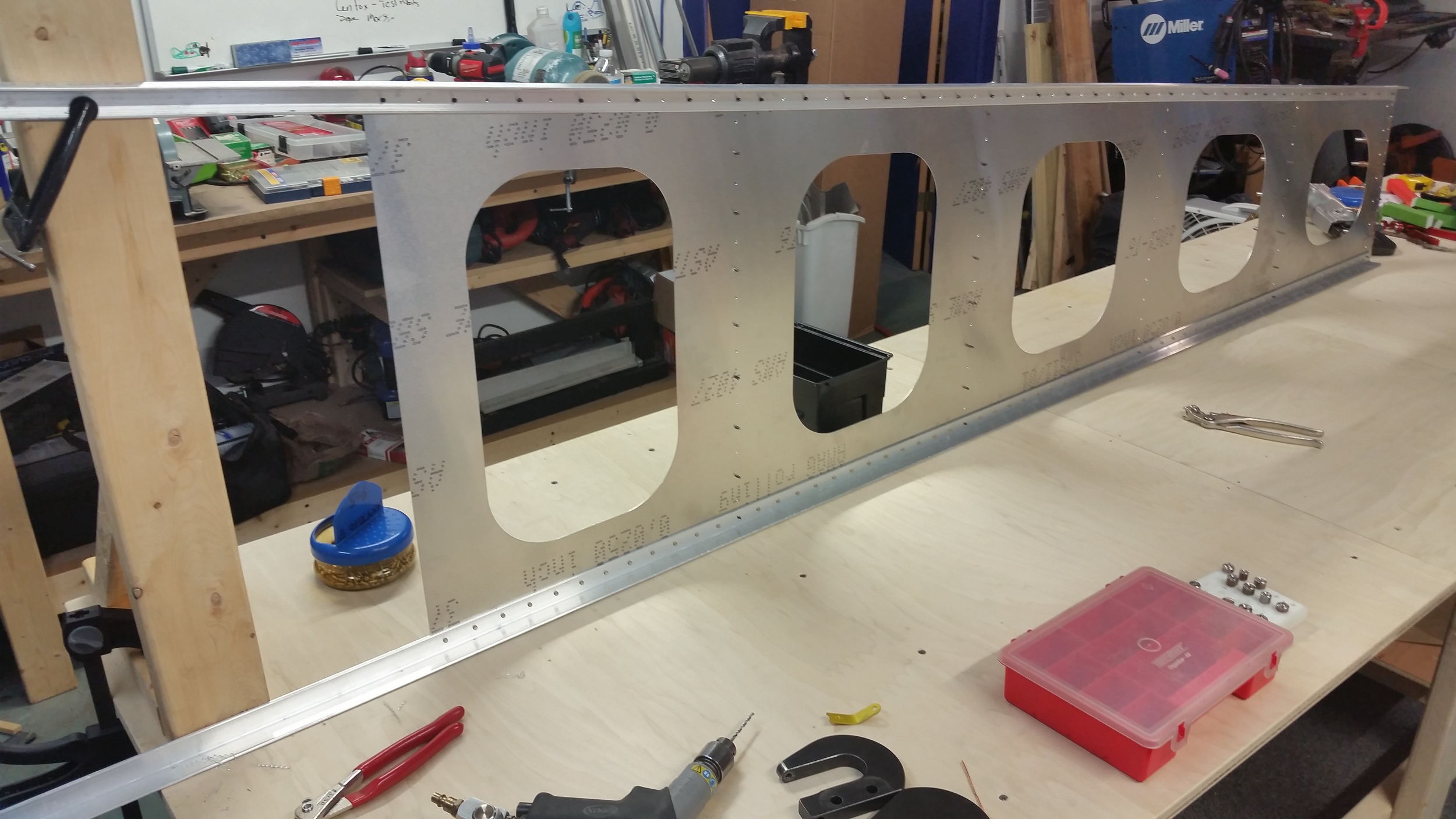
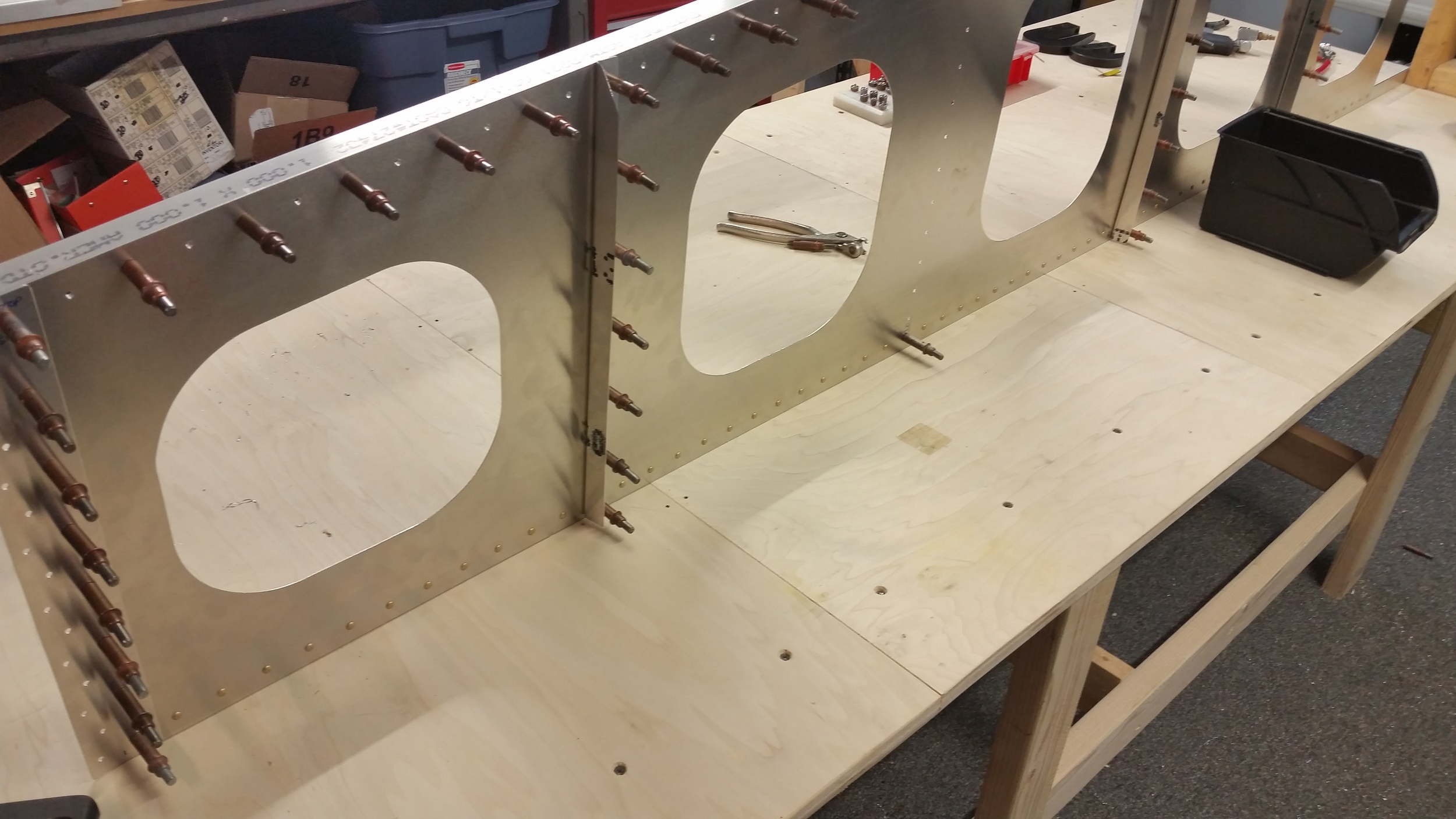
And so we started doing some assembly. The process is pretty simple, though there's plenty of work involved. If you're building an aluminum plane I guess most situations call for a ton of rivets and this is one of them. It does make me think about going to something like a bonded construction: it's a simple enough form that I can see almost like pre-applied epoxy with tapes that you pull before assembly, or some kind of procedure like that. There's enough precedent that it might not be crazy.
For now though, holes, rivets, repeat.
As we finish this up over the next few days we'll post more pictures that show the overall form.