Building a Box
So things have been moving along since finishing the Vertical, we're on to making a box. To elaborate, its a long sturdy box that will be the core of the fuselage frame. This build is specifically for a load test: the piece will be loaded to 9 g’s in increments – just as we did with our horizontal test piece. We are again looking to see how the sample will differ from the calculated expectation, and also whether this design as-is handles the load it will need to in flight, and to what degree over or under that is. I guess they are different aspects of the same problem; in my eye the pragmatic "does it work" viewpoint is the ultimate goal regardless, but having models agreeing to that end seems important. I'm not claiming to be the numbers man.
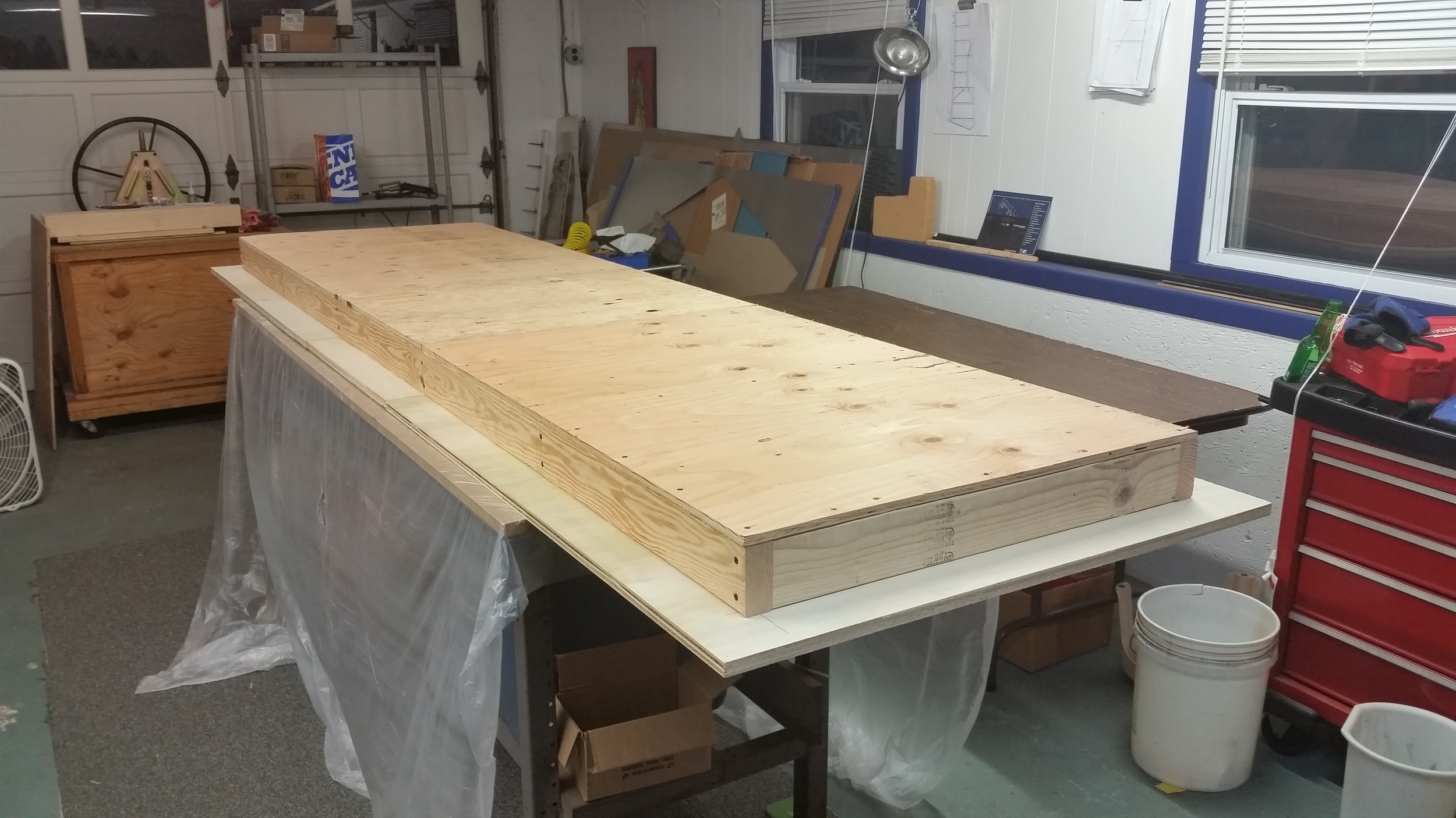
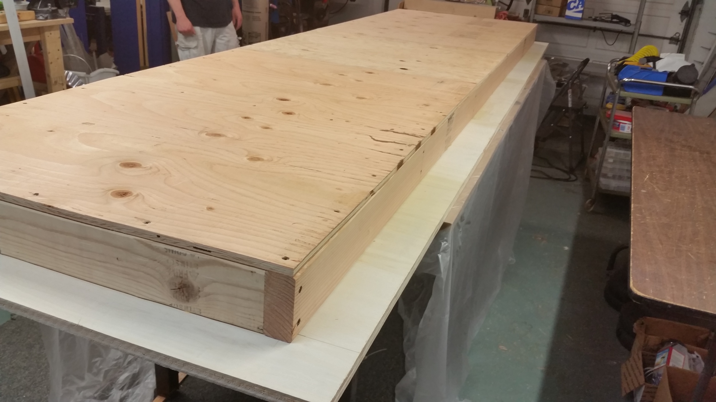
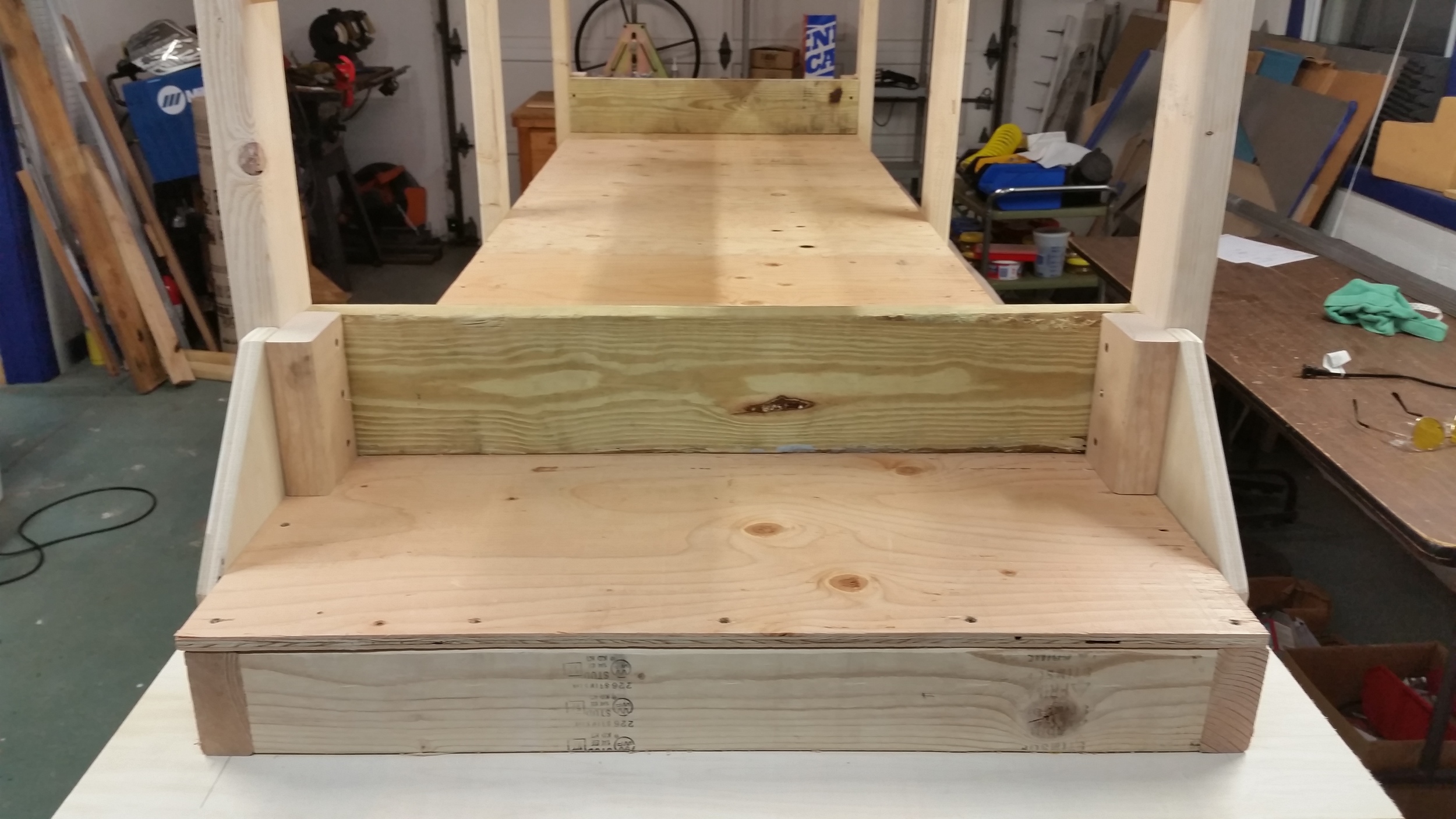
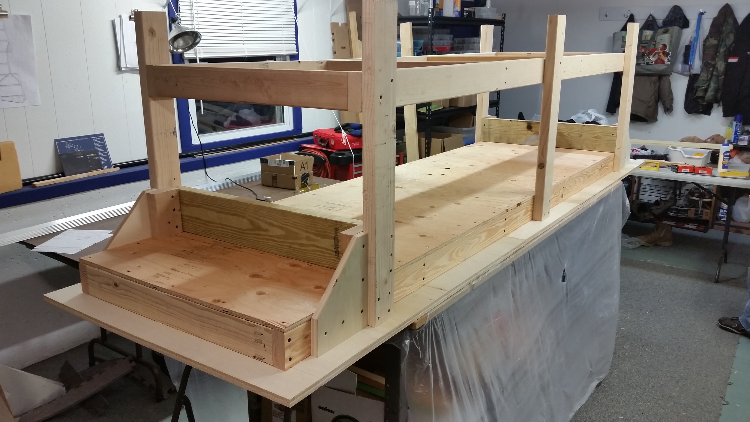
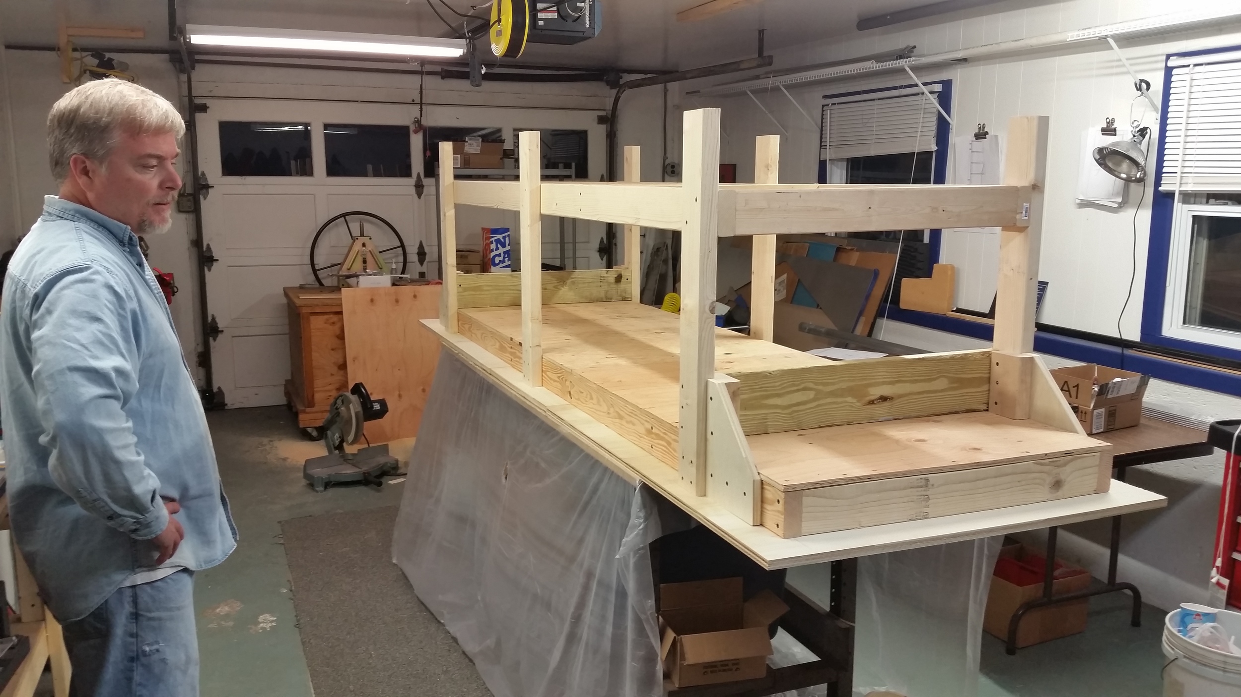
So before we even get into the actual fuselage stuff, I mentioned last update we were building a table from plywood and such. Well, yes, we have a table now. It's not a perfect plane, we diddn't plane every board to within .005 of an inch or anything, but it's about as dead flat as you need for building your aircraft on, easily less than 1/16 deviation over the thing. So here's what that looks like:
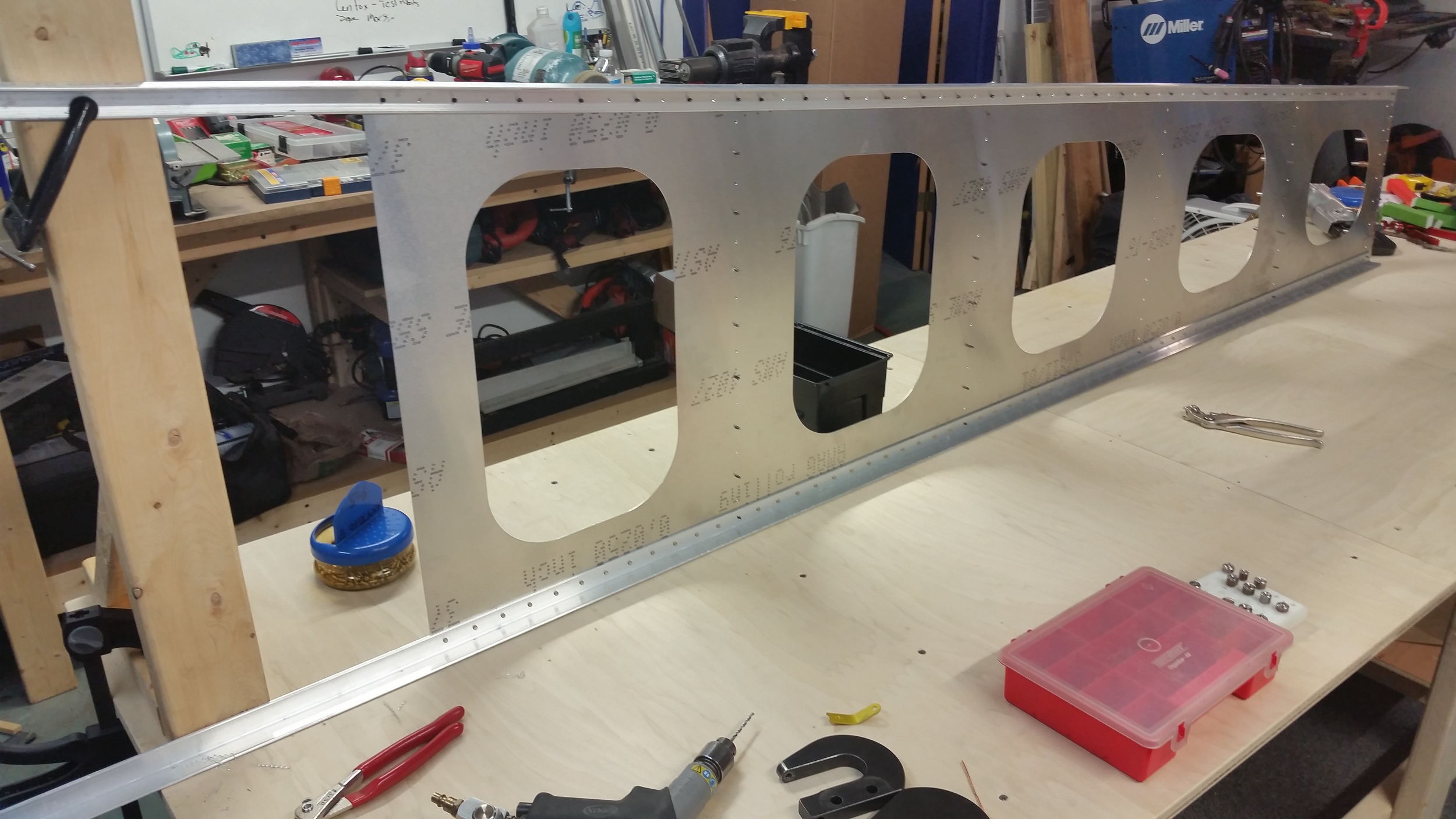
The aft fuselage that we're sampling here, goes from a bulkhead behind the rear seat of our main cockpit box, all the way down to the tail post. The design is very straightforward; 4 longerons made of of L-channel tie together 4 side-sheets to form a long box. Stiffeners and a few bulkheads are evenly spaced along the length to tie everything together, prevent buckling or twisting, and in the final full fuselage built the stiffeners actually act as attachment brackets for the outer skin bulkheads and stiffeners. Those will inevitably add extra support but the hope of the design is to make this box self-sufficient for the intended loads, and give us the flexibility to hang any type of outer shapes we wish. That's the whole objective here of ScaleBirds anyway right? Make it easy to go wild later.
For the build, I had to first generate good CAD data. I had a design in 3D already, but I had to further detail the aft part of the fuselage design in Inventor from where it was originally, mainly adding holes and details wherever it was needed. It took a while and I feel like the master-modelling method I'm using on the fuselage is reaching the limits of practicality; I started seeing crashes and long-long delays to update the feature tree after a change. At some point, I'll probably be having to go in and re-model the entire frame from smaller files once we have dimensions we like. The ideal would be to break it down to where each panel and part of metal gets its own part file, but it makes for a convoluted assembly where everything has to be interlocked anyway, so I figured doing it all in-situ in a single part file would give me greater flexibility while fleshing out the design and avoiding over-use of problematic reference dimensions. The good news is that unlike all the aerodynamic surfaces I've been having to deal with lately, I can directly model everything and export it to 2D as its all flat and I don't have to worry about curved-surface distortions and such. This means when I output the files into 2D I get true geometry that can be cut.


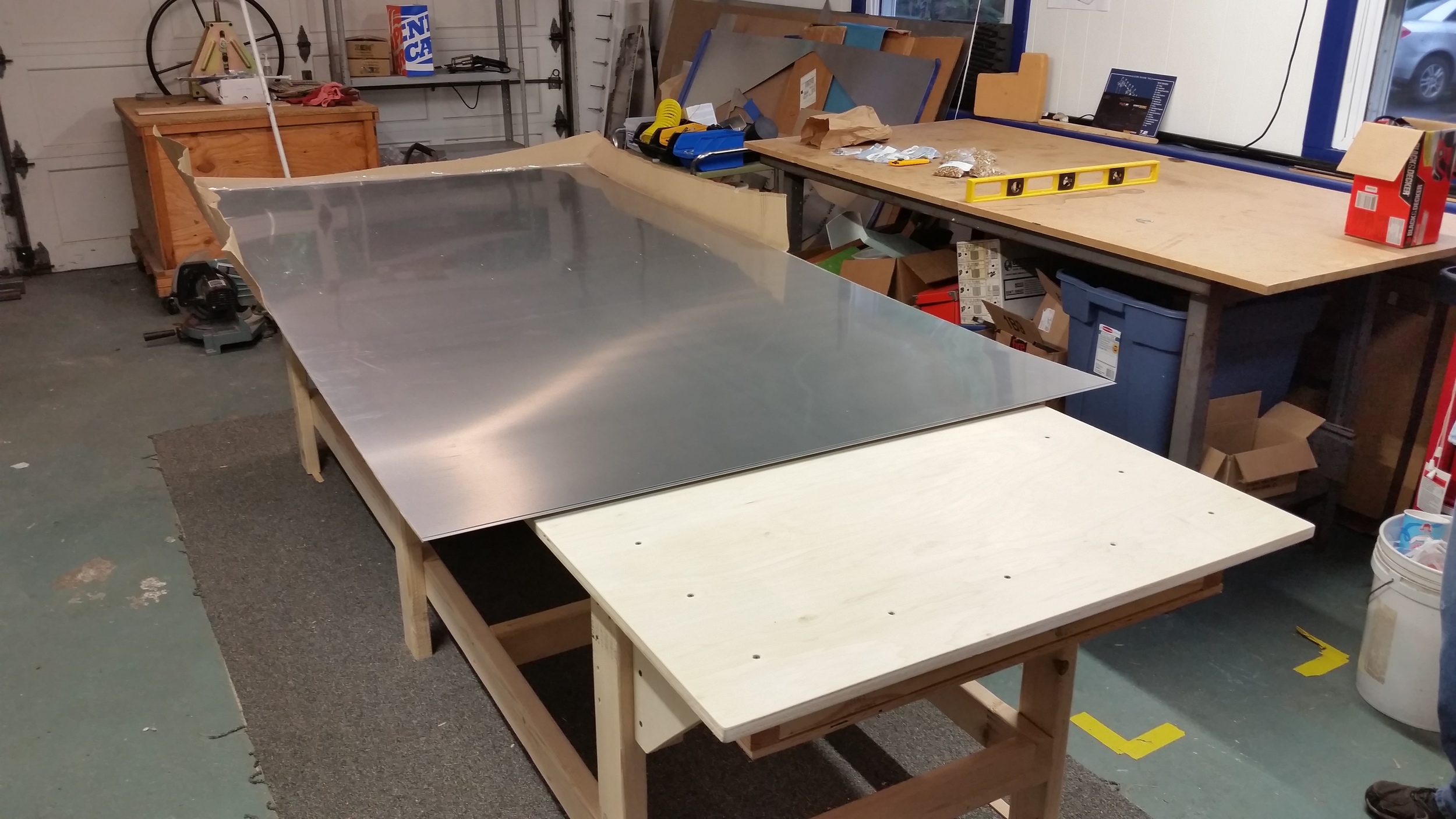
So it came to cutting out parts. I rigged up the patterns into CUT2D, and proceeded to cut the main panels from a pair .025 sheets. (The aluminum sheet we ordered from Aircraft Spruce, and chose to get it rolled for shipping which cut the delivery cost by a significant amount. I wasn't able to find much of any reference to ordering aluminum in this manner online, so we just took a gamble that the resulting sheet would unwrap flat. Turns out it does, it springs right back to flat condition as if nothing happened.)
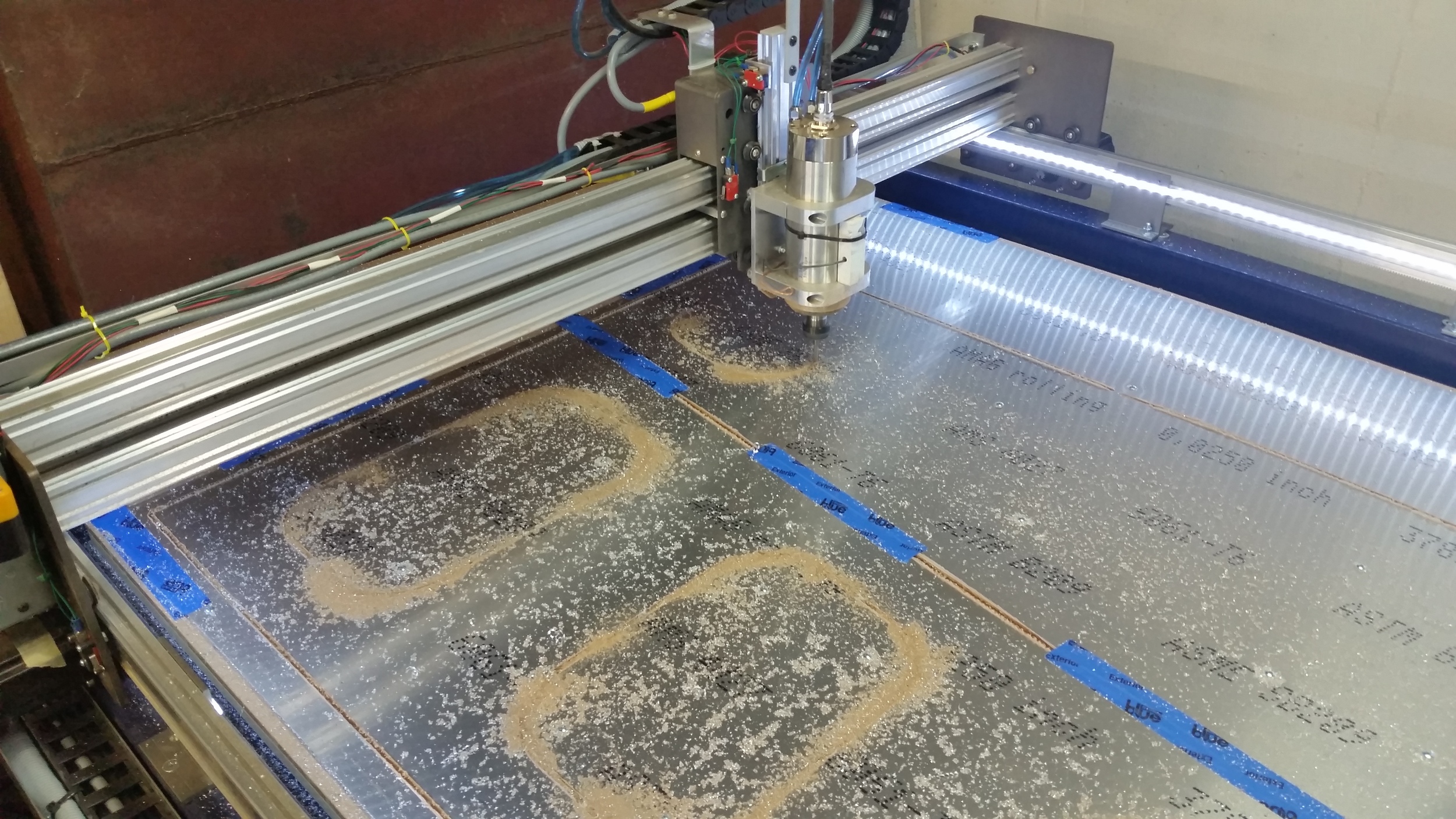
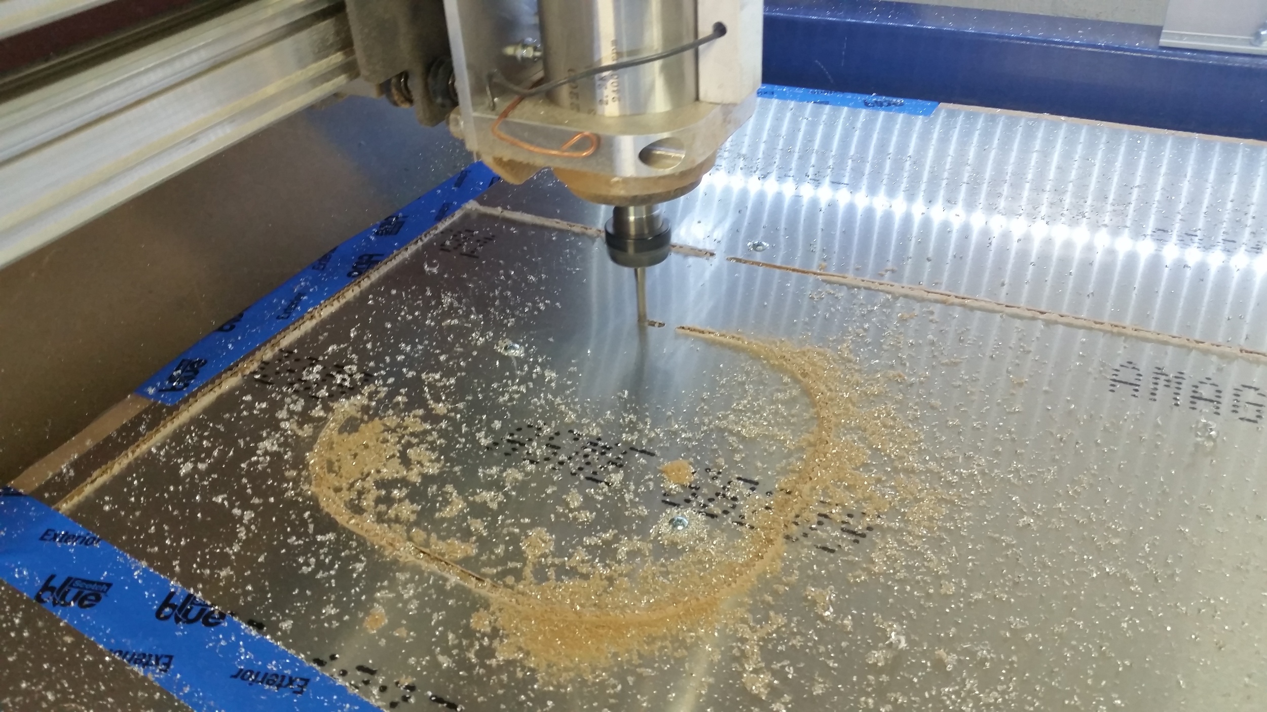
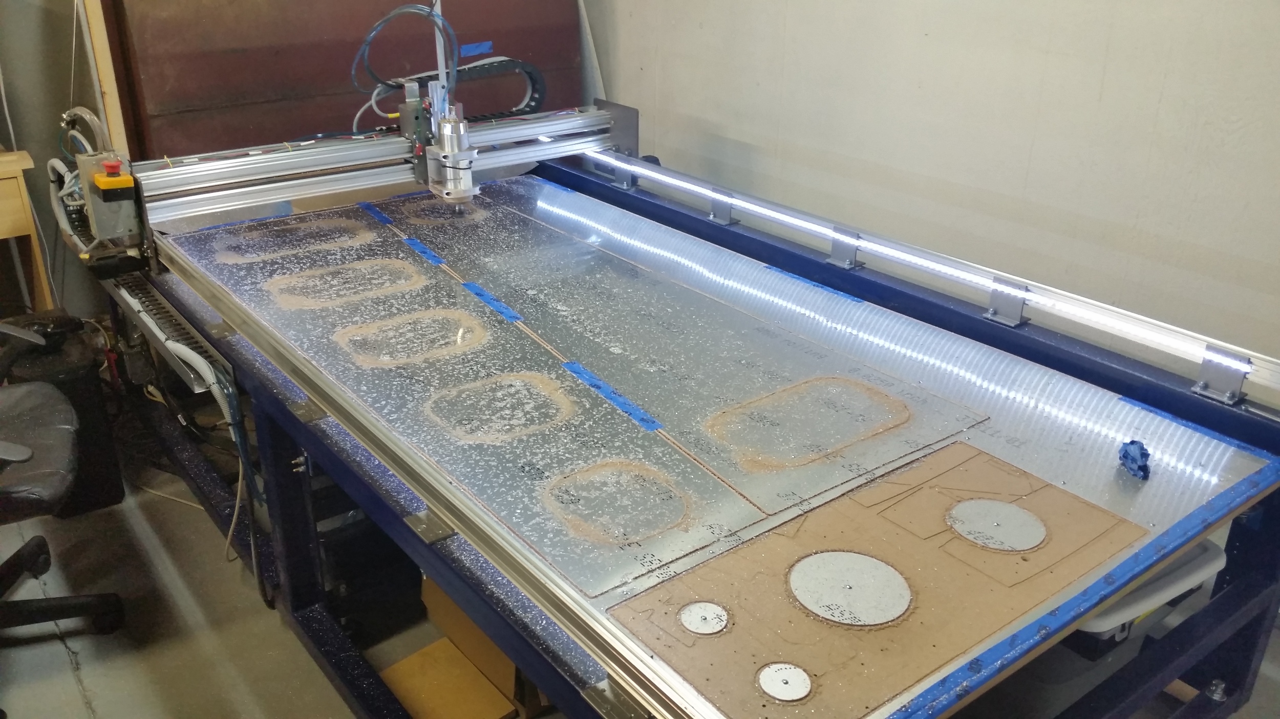
So, Then we set to making some smaller parts that are made of thicker materials, flanges, doublers, etc. Some stuff is left to cut still, where we had to order more materials; but either way, the parts we did do came out looking great.
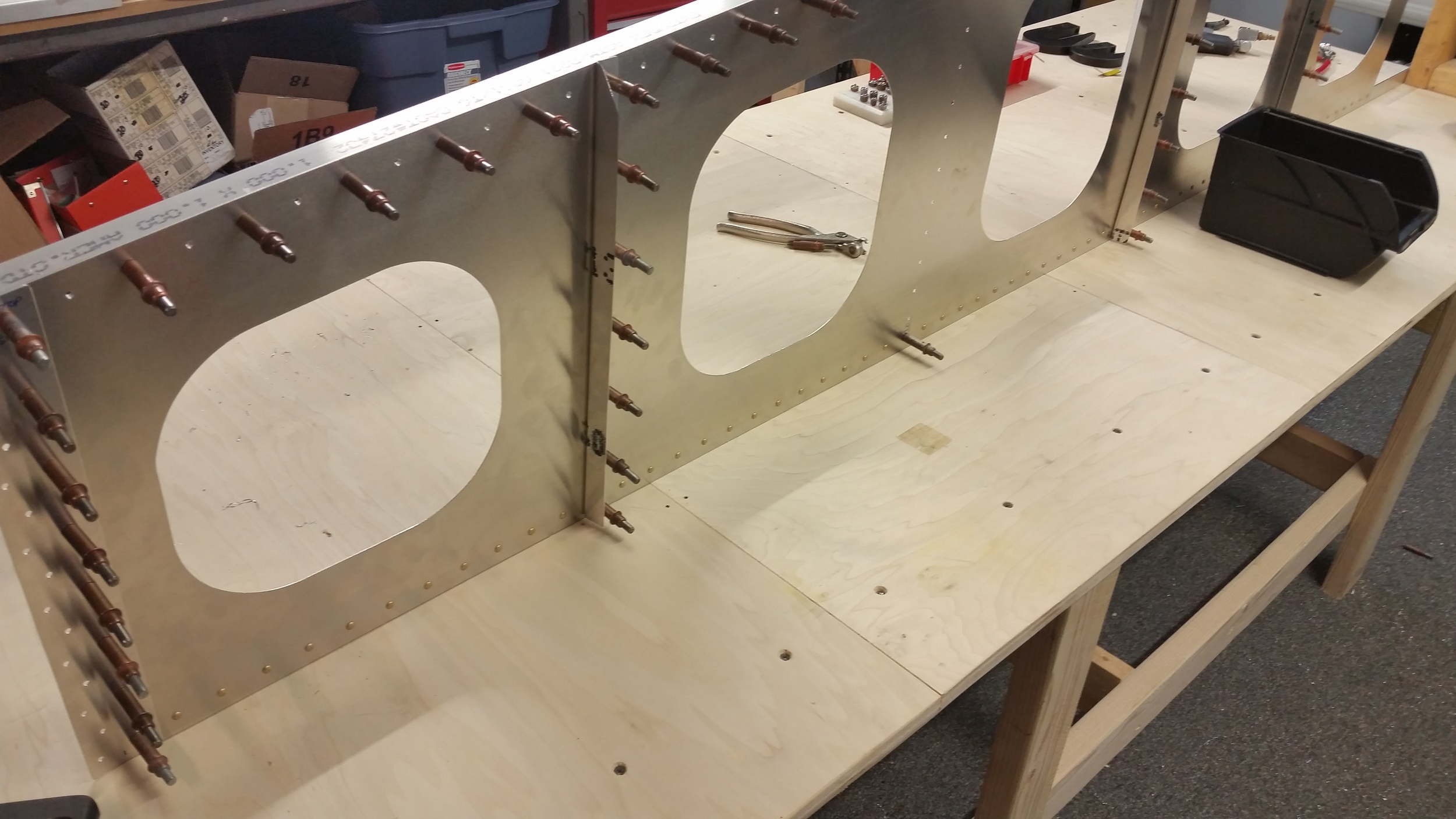
And so we started doing some assembly. The process is pretty simple, though there's plenty of work involved. If you're building an aluminum plane I guess most situations call for a ton of rivets and this is one of them. It does make me think about going to something like a bonded construction: it's a simple enough form that I can see almost like pre-applied epoxy with tapes that you pull before assembly, or some kind of procedure like that. There's enough precedent that it might not be crazy.
For now though, holes, rivets, repeat.
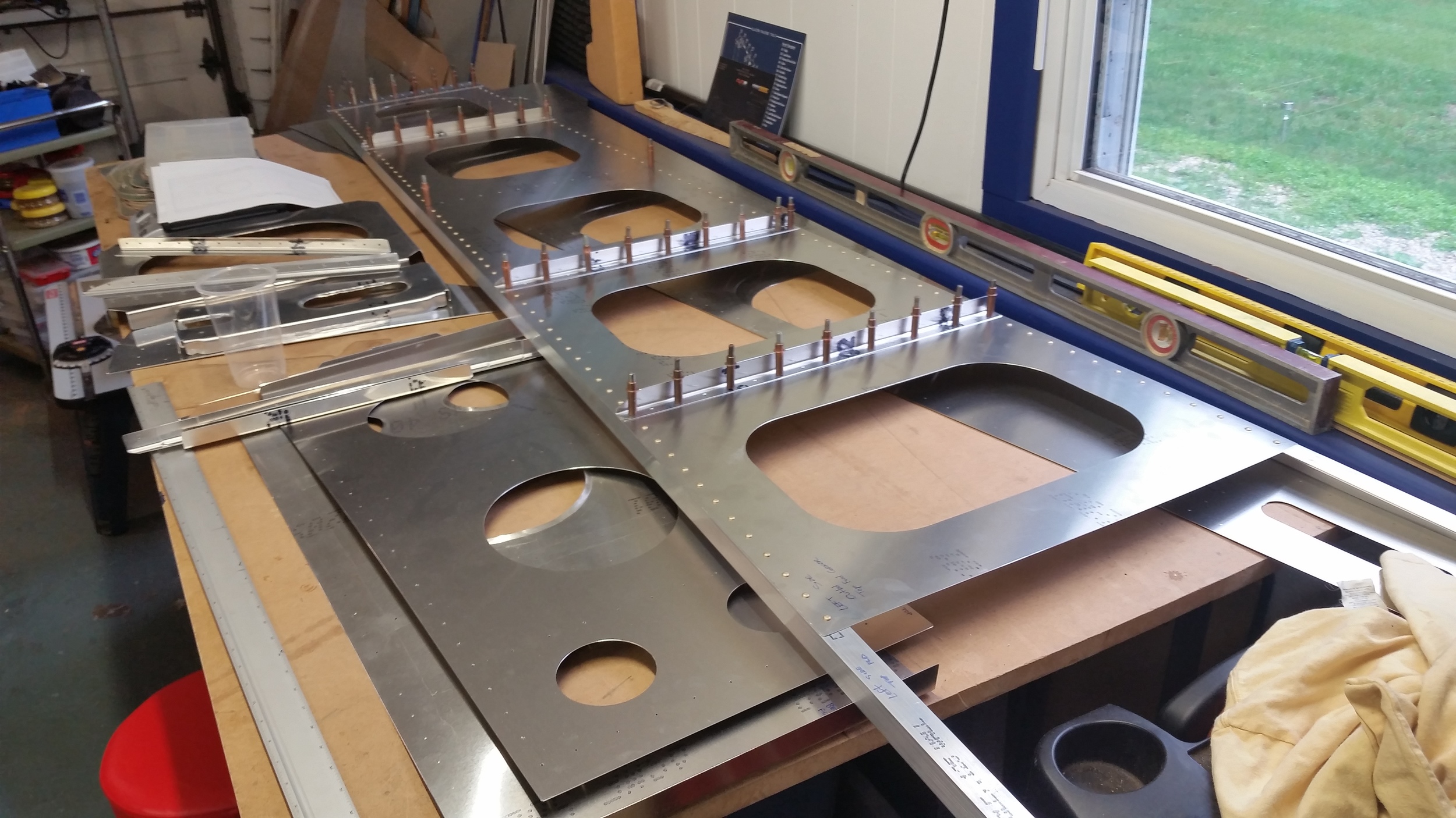
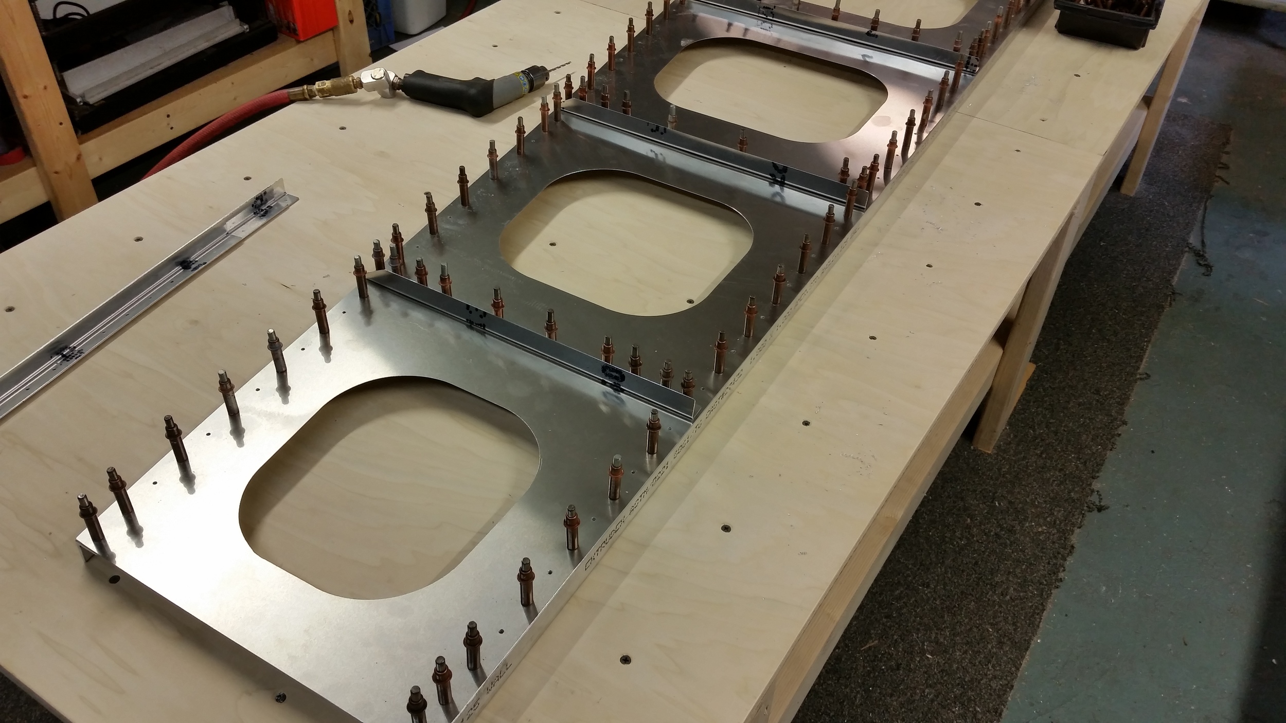
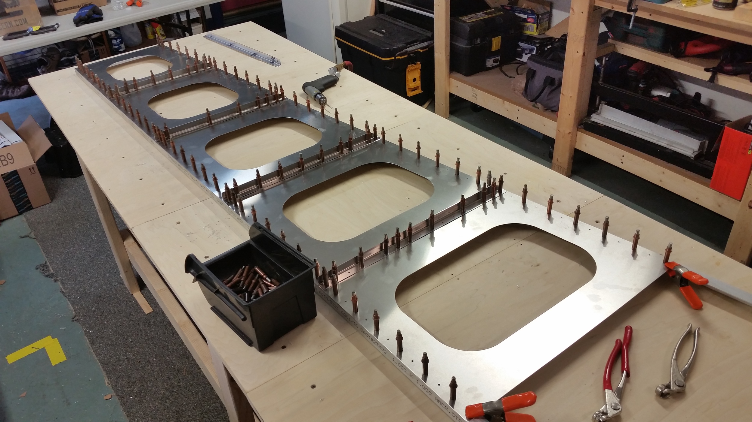
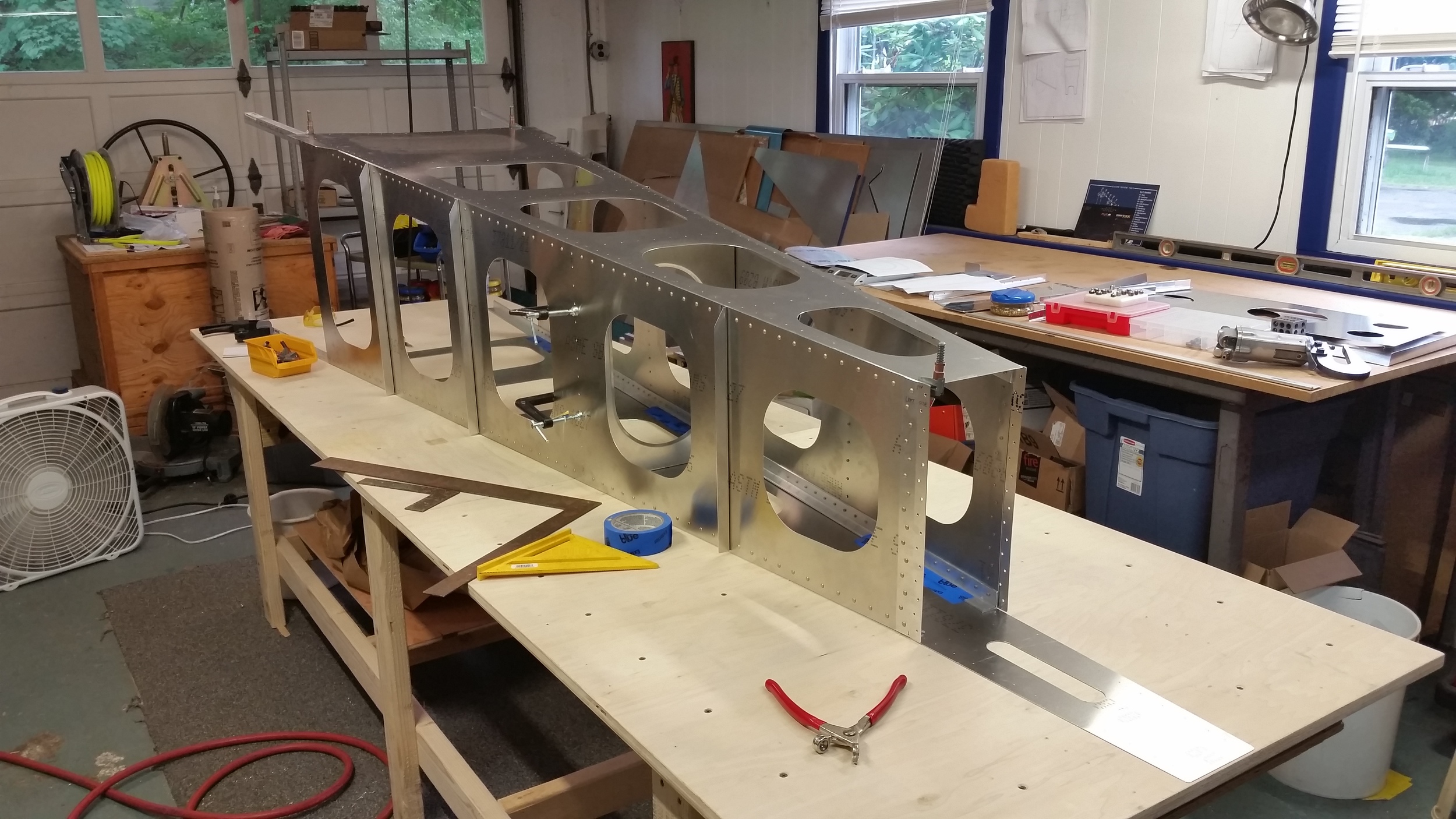
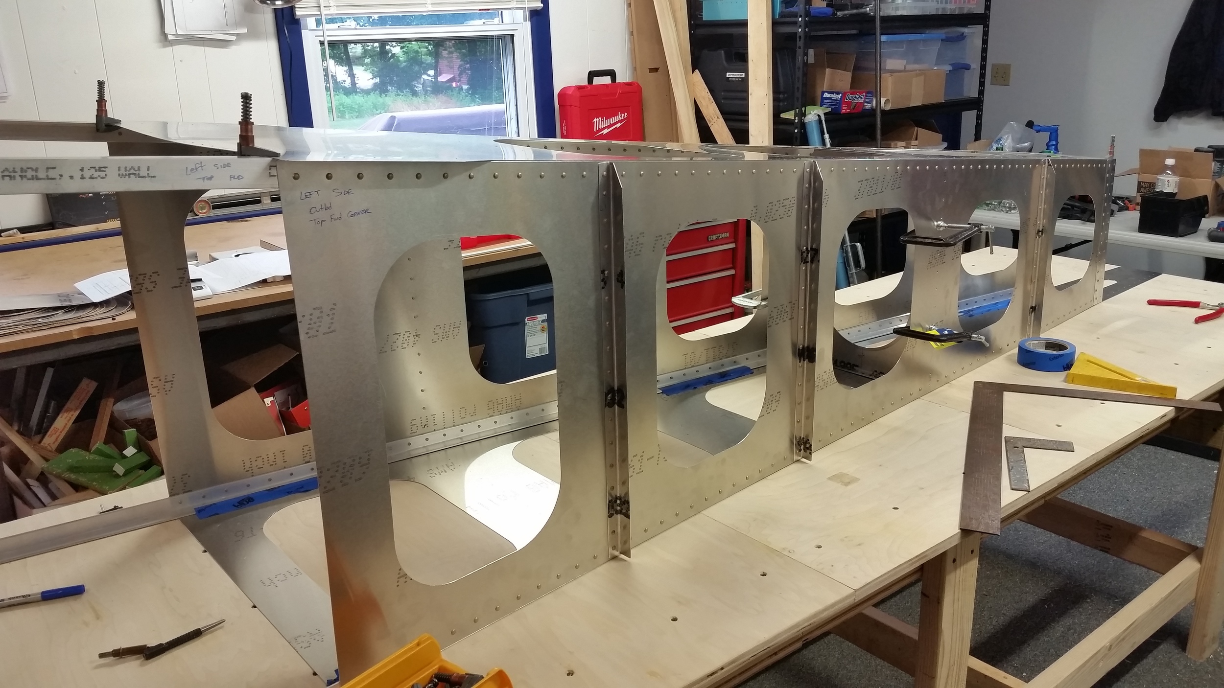
As we finish this up over the next few days we'll post more pictures that show the overall form.
