Elevator Structure Build
In our first work towards flight articles for the Hellcat, we were able to try out various methods and processes for turning the 3D CAD model into flat parts and back into 3D physical structure. It had a few delays due to design, or supply, or just other commitments, but in all the time spent wasn't too bad, especially if you only count hours towards the final product. Considering how detailed the result is, the build is fairly straightforward.
We learned things about the process and design that will be changed next time we put one together, and those lessons have already informed the Rudder and Aileron designs, and just general SOP for CNC use. If you're interested to see more, read more to see a more detailed account of our build process.
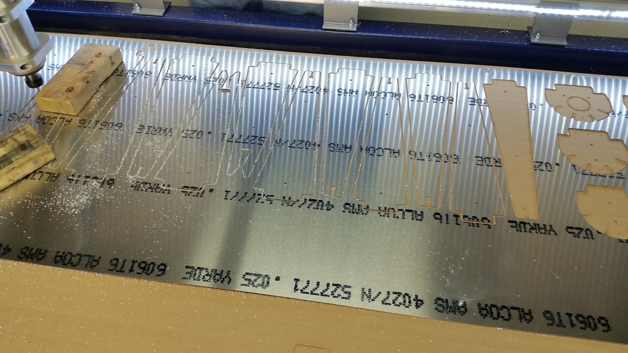

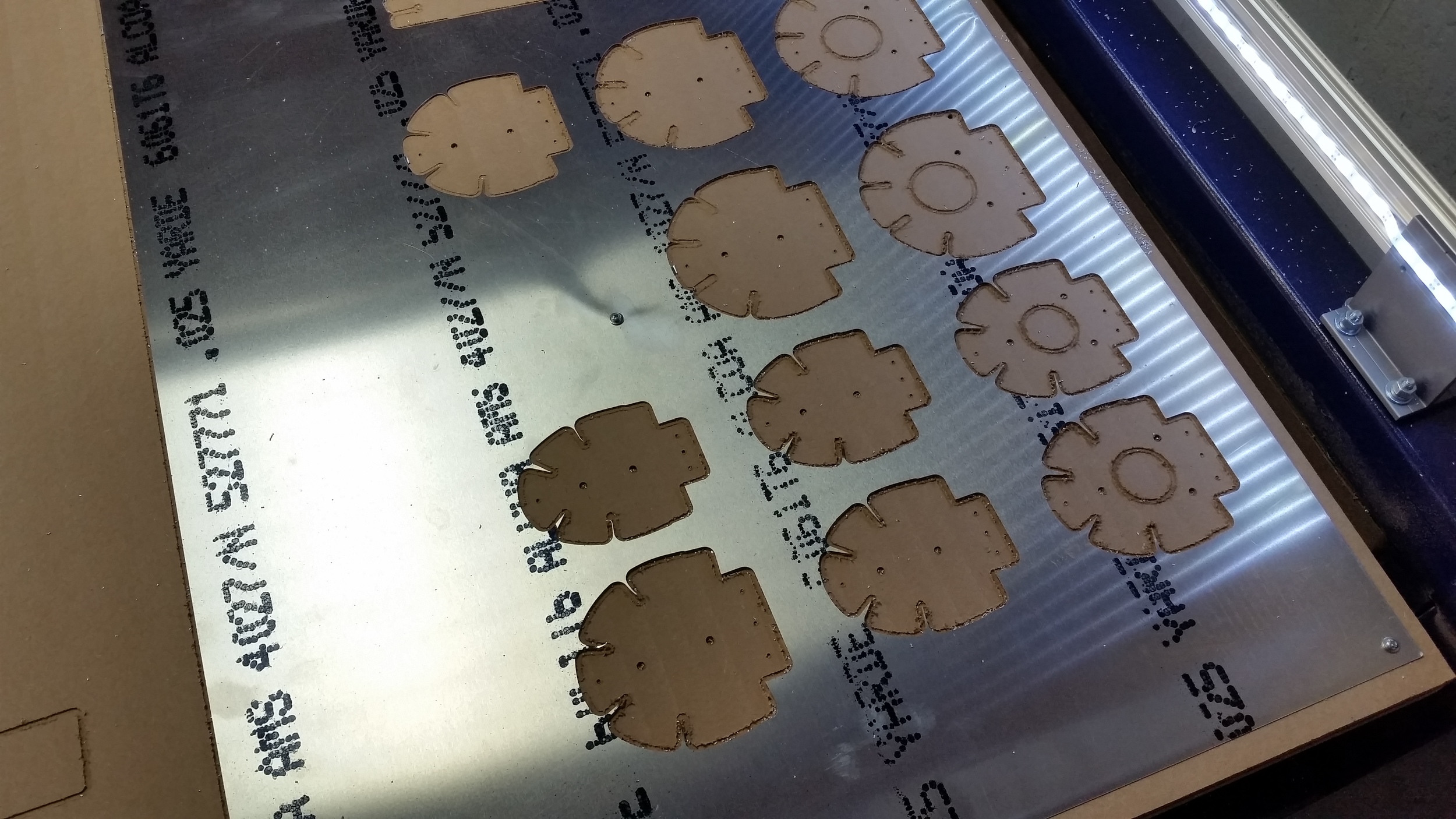

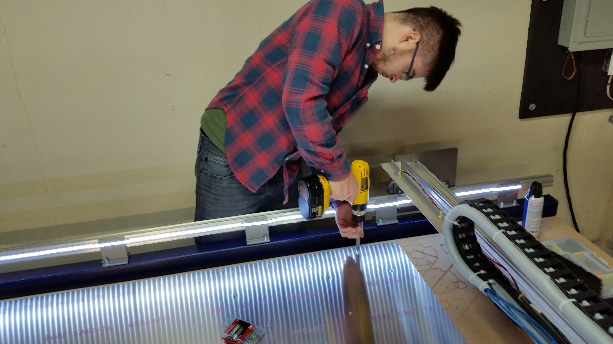

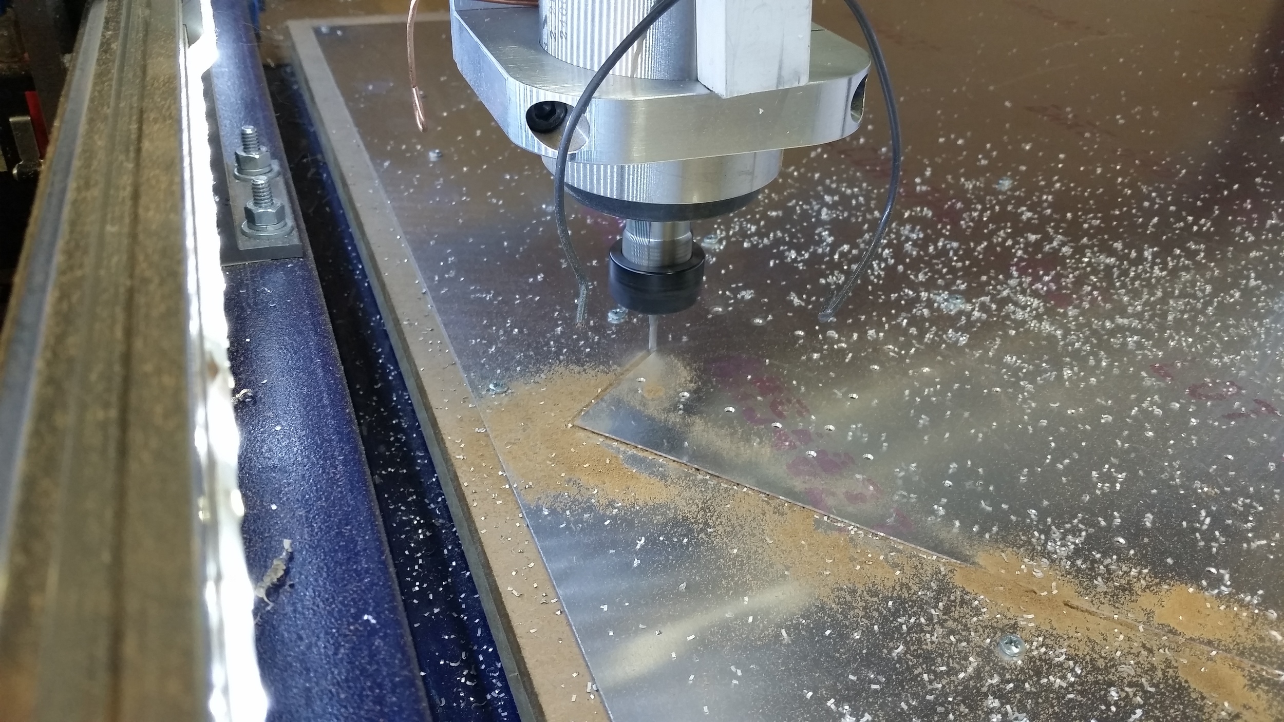
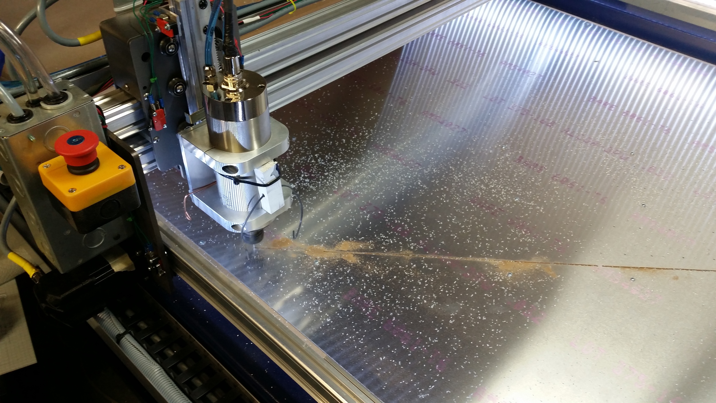
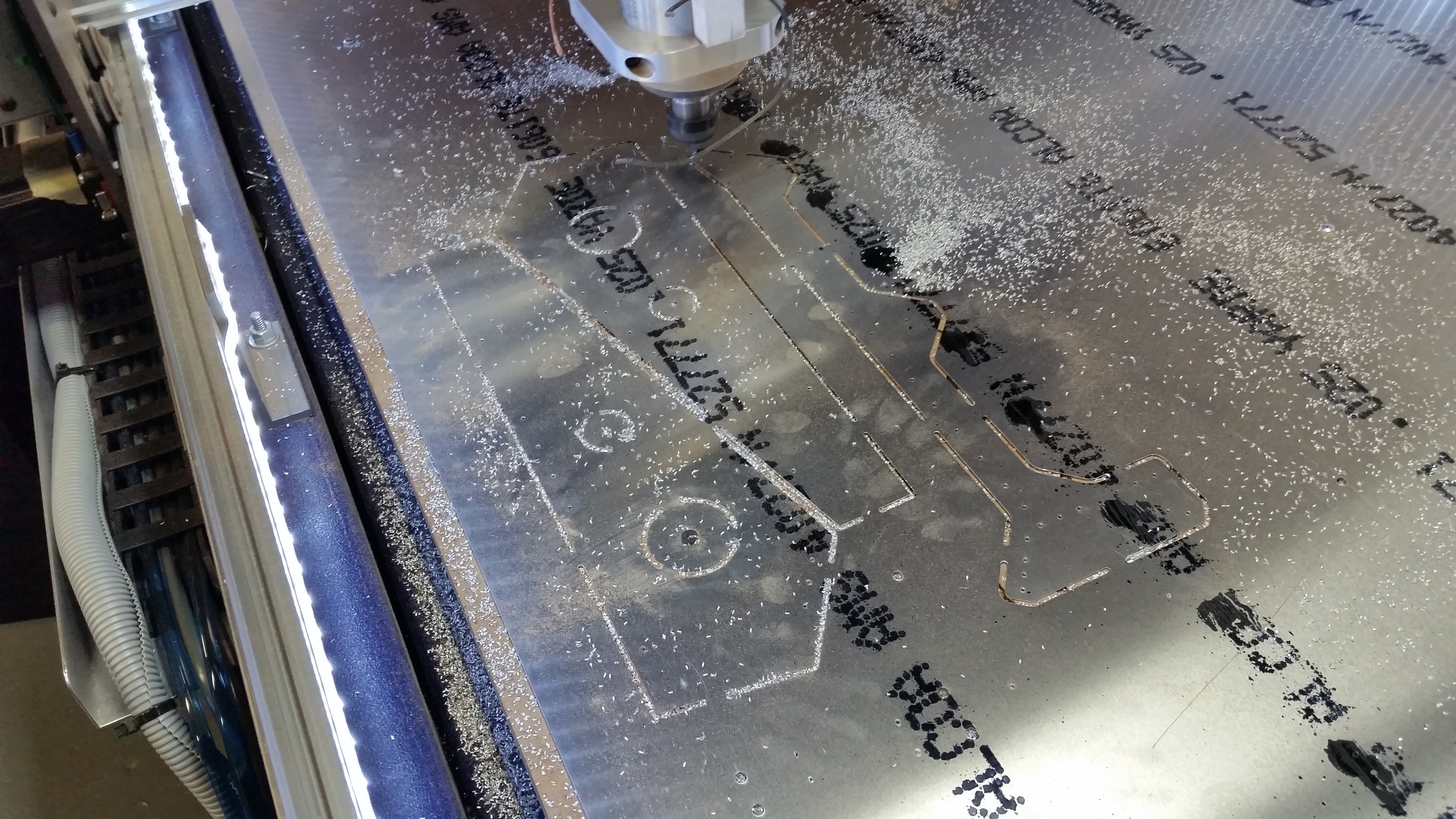

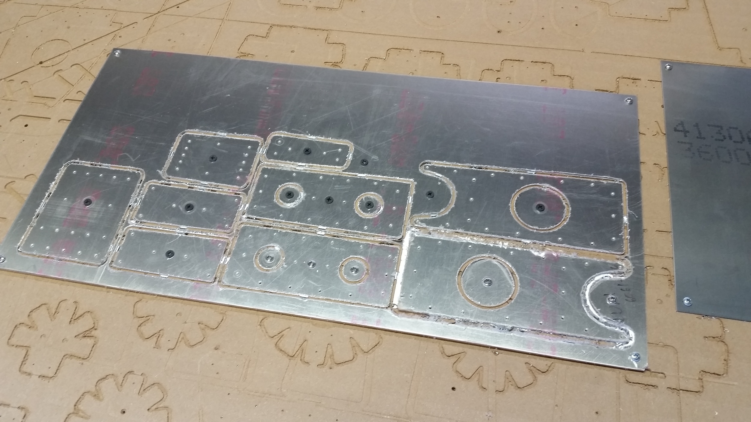

Having a CNC router table really is great for an aircraft builder. So much of it relies on turning sheet goods into small parts, and especially in the case of metal parts where shapes and holes must be accurately cut and drilled in relation to each other.
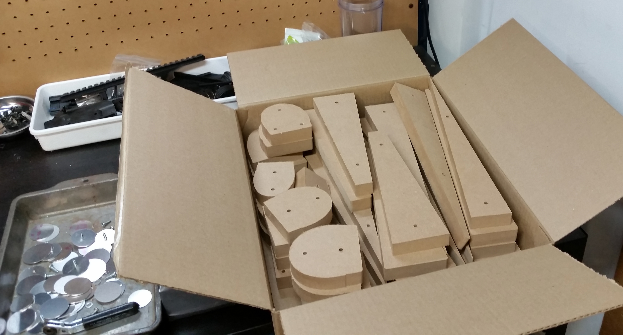
We used the router to cut our aluminum sheet, making rib blanks, spar blanks, and even the skin flats. All of these parts have to be bent. Some on the break, but some into custom shapes. So we used the router to cut MDF forming blocks as well.
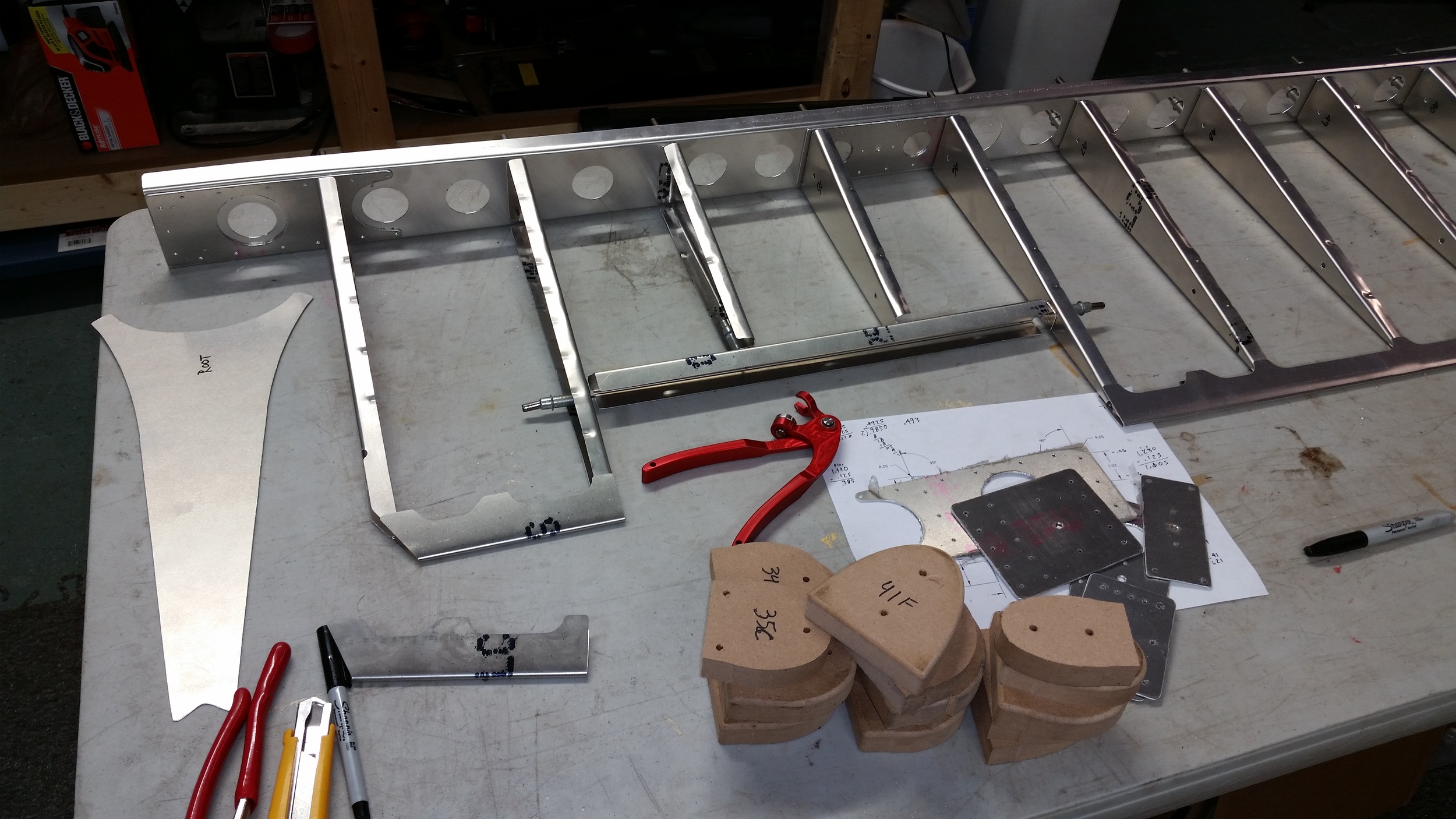
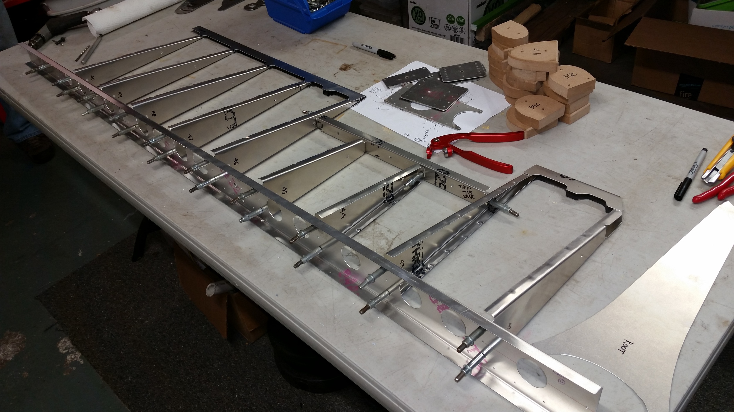
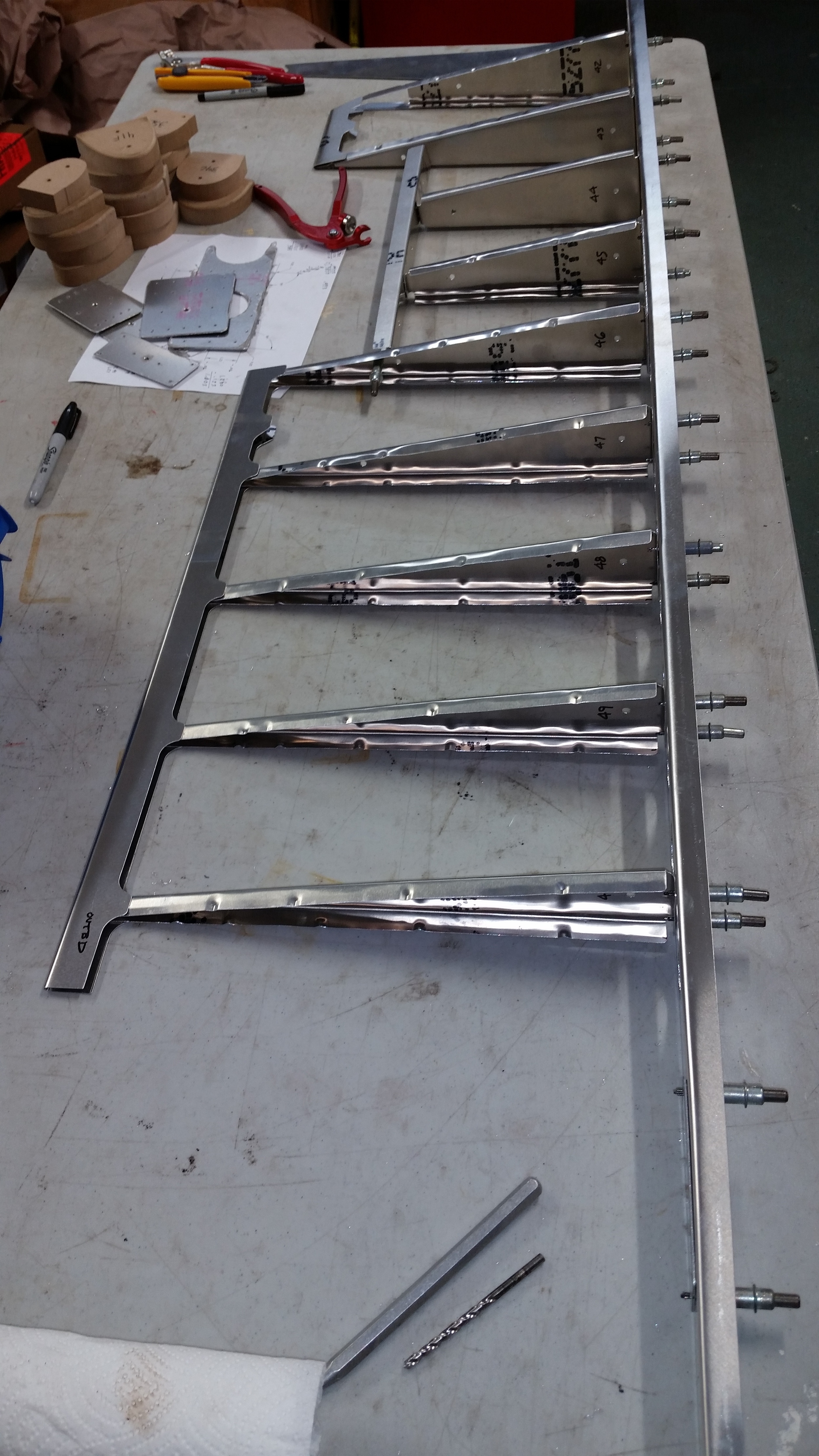
Once cut and formed we were able to cleco together a number of parts right away. But that didn't provide really a structure ready to drill and rivet; as much as it all looked right, there was no guarantee it would end up square and true on their own.
Another thing that was apparent after getting to this stage was that reversing the flange direction on the spars would have been ideal. We figured it was a little late to change the design, and that it'd be worth moving forward as-is, but it did mean a number of pull rivets would be needed to secure the leading edge to form a solid D-section.
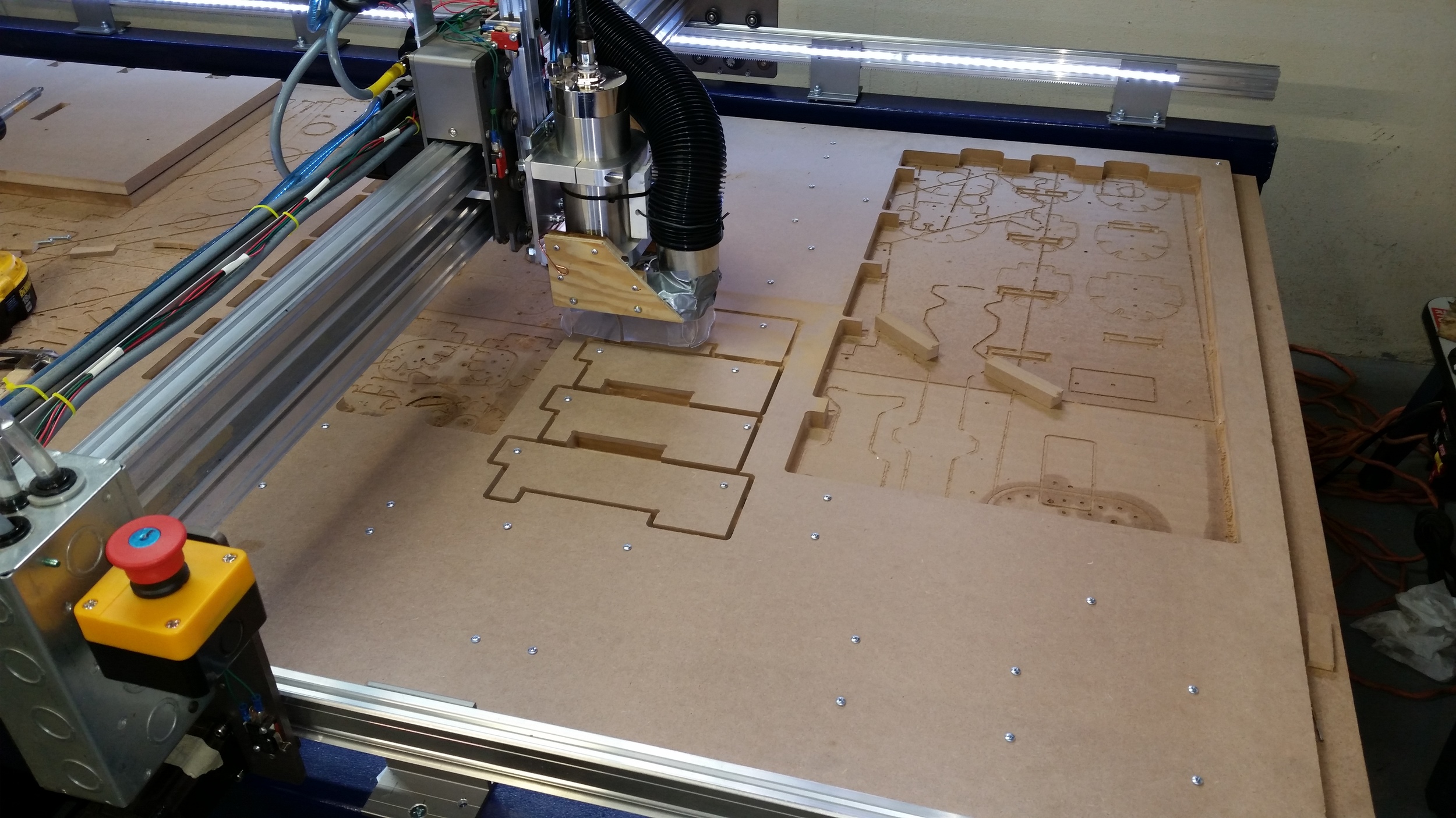
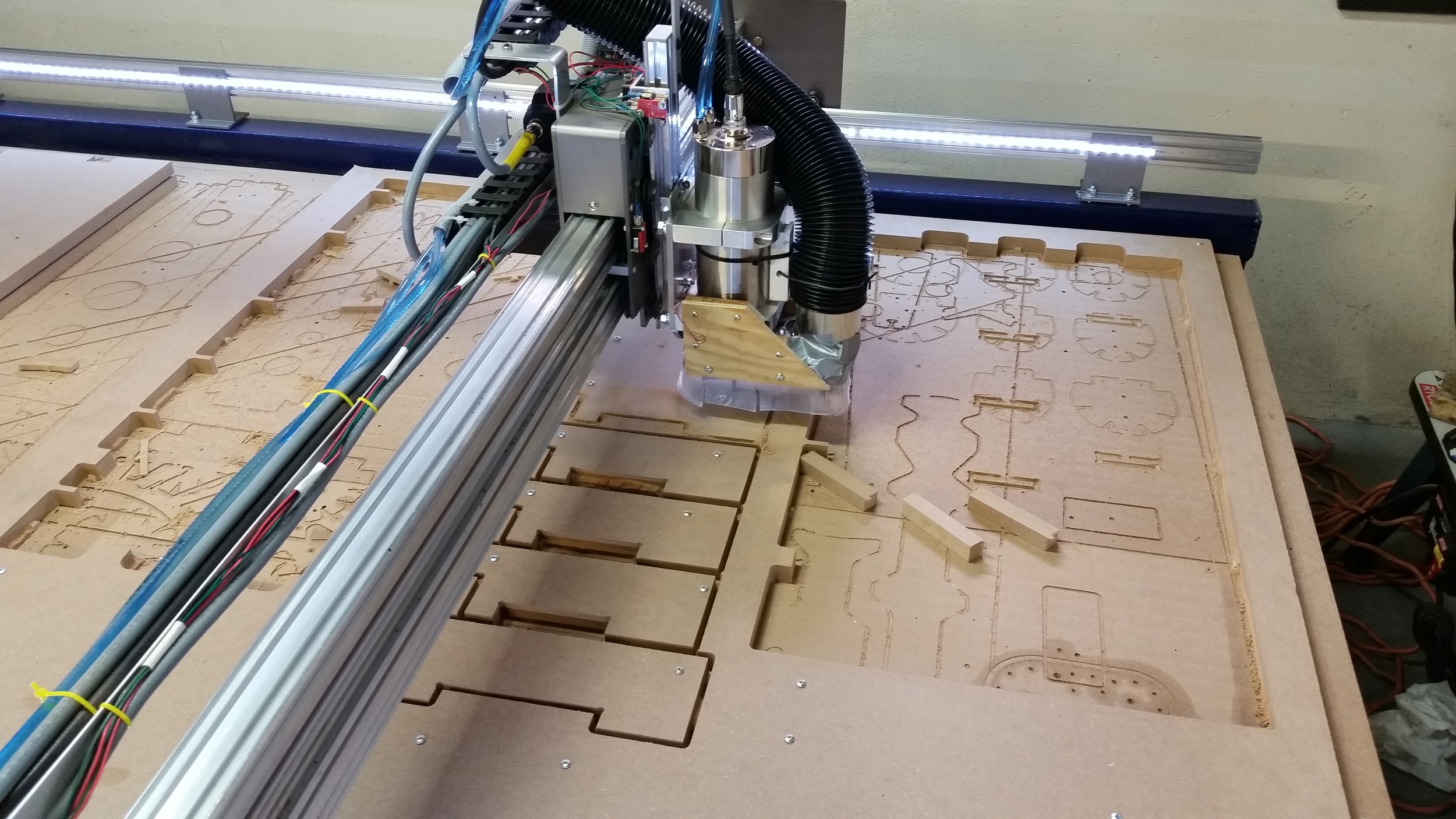
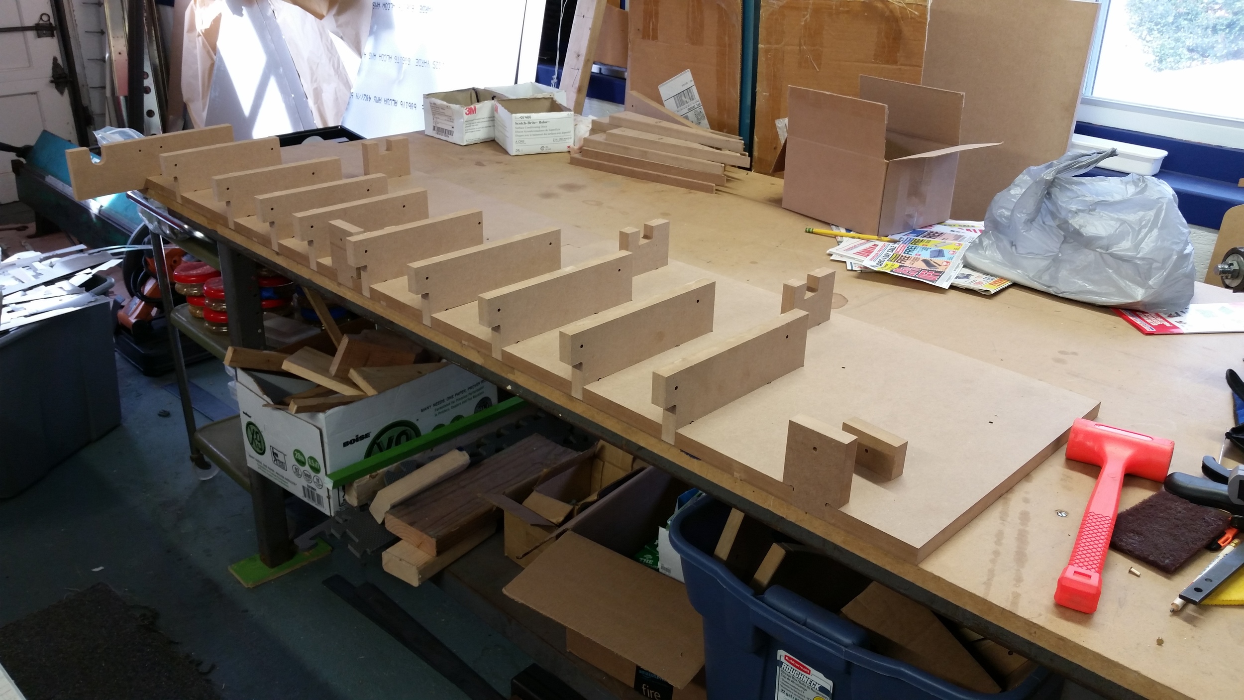
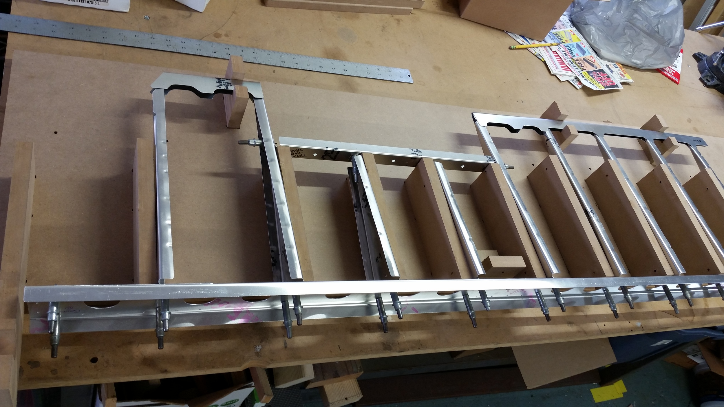
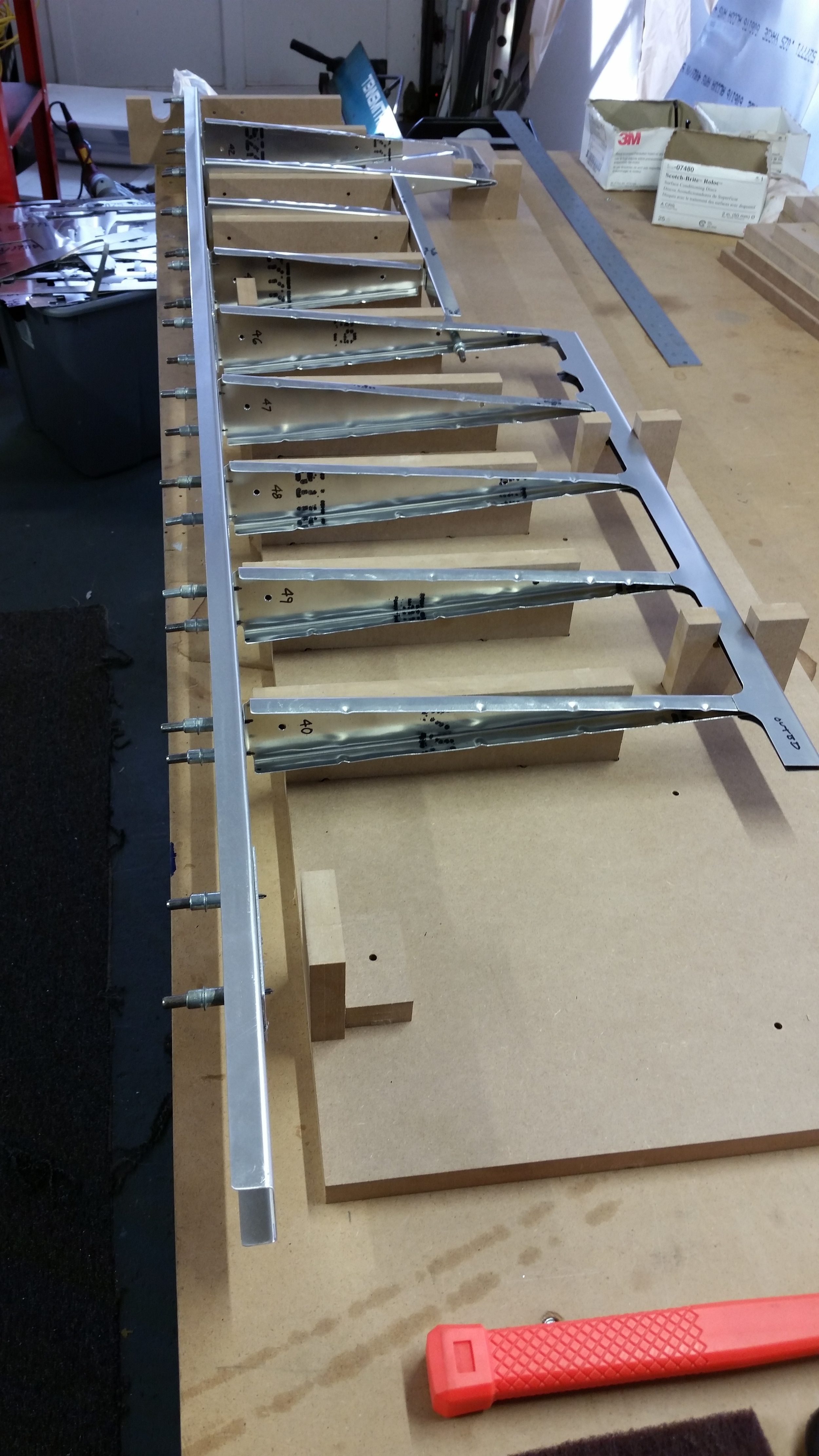
In order to get everything put together properly it was apparent we'd want a good fixture. So in 3D one was modeled and transposed into patterns complete with dogbone reliefs and alignment holes. When cut on the router, everything came out surprisingly nice, and fit together tightly but not too much so.
It shouldn't be that surprising that the machine is as accurate as it is, but because it was our first attempt at such a thing, its hard to grasp just how good we have it.
With the fixture in place it was possible to bolt up all of the ribs and the spars, and get everything rather nicely square.
But as the fixture is rigid and accurate, a few small inconsistencies did come forth from the aluminum parts. A few holes that were slightly out, a part here or there needed to have the flanges tweaked. These were traced back to operator error in the CAD, not the machine, and new parts were made in some cases.
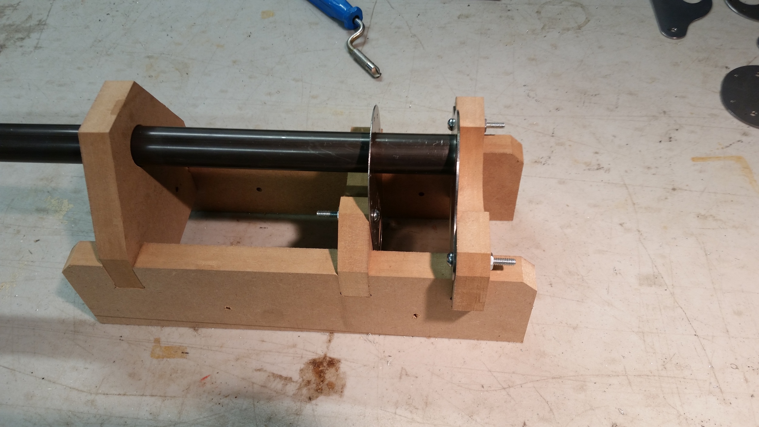
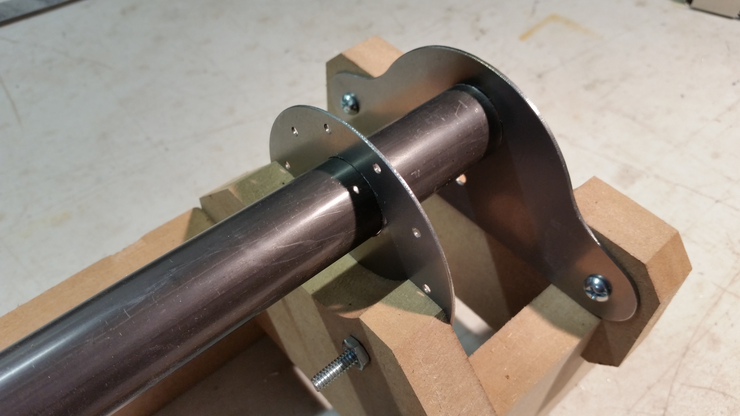
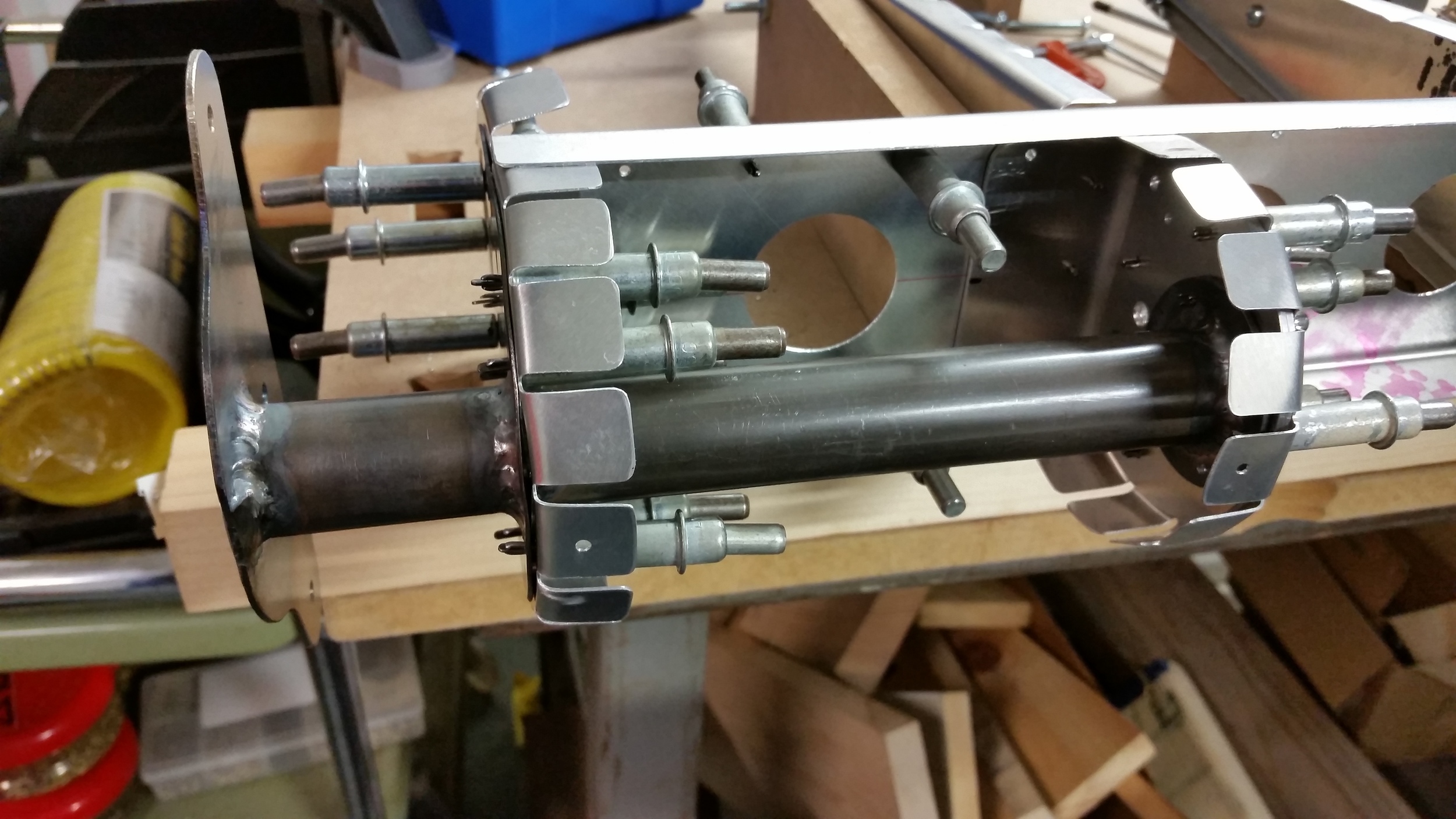
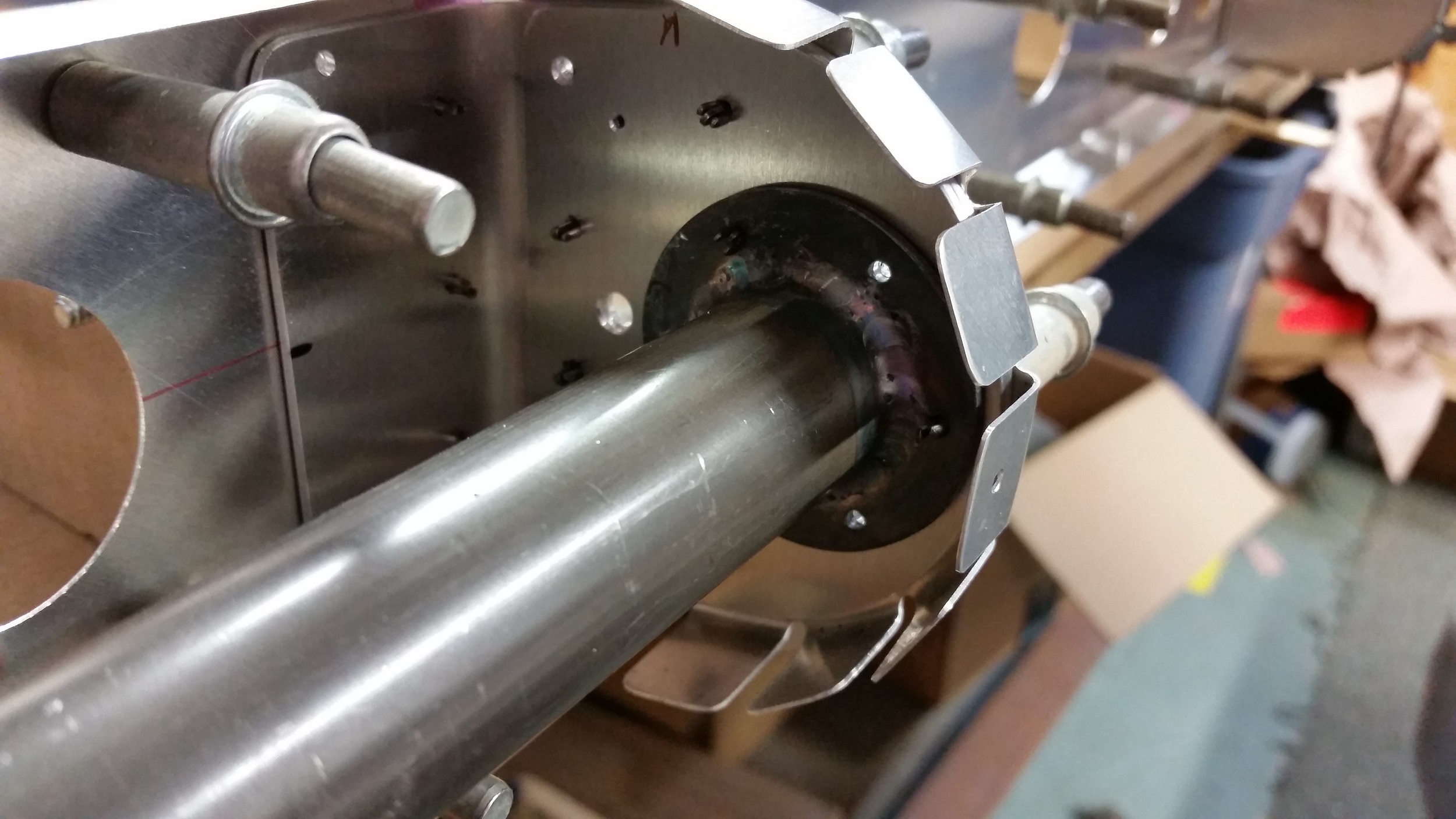
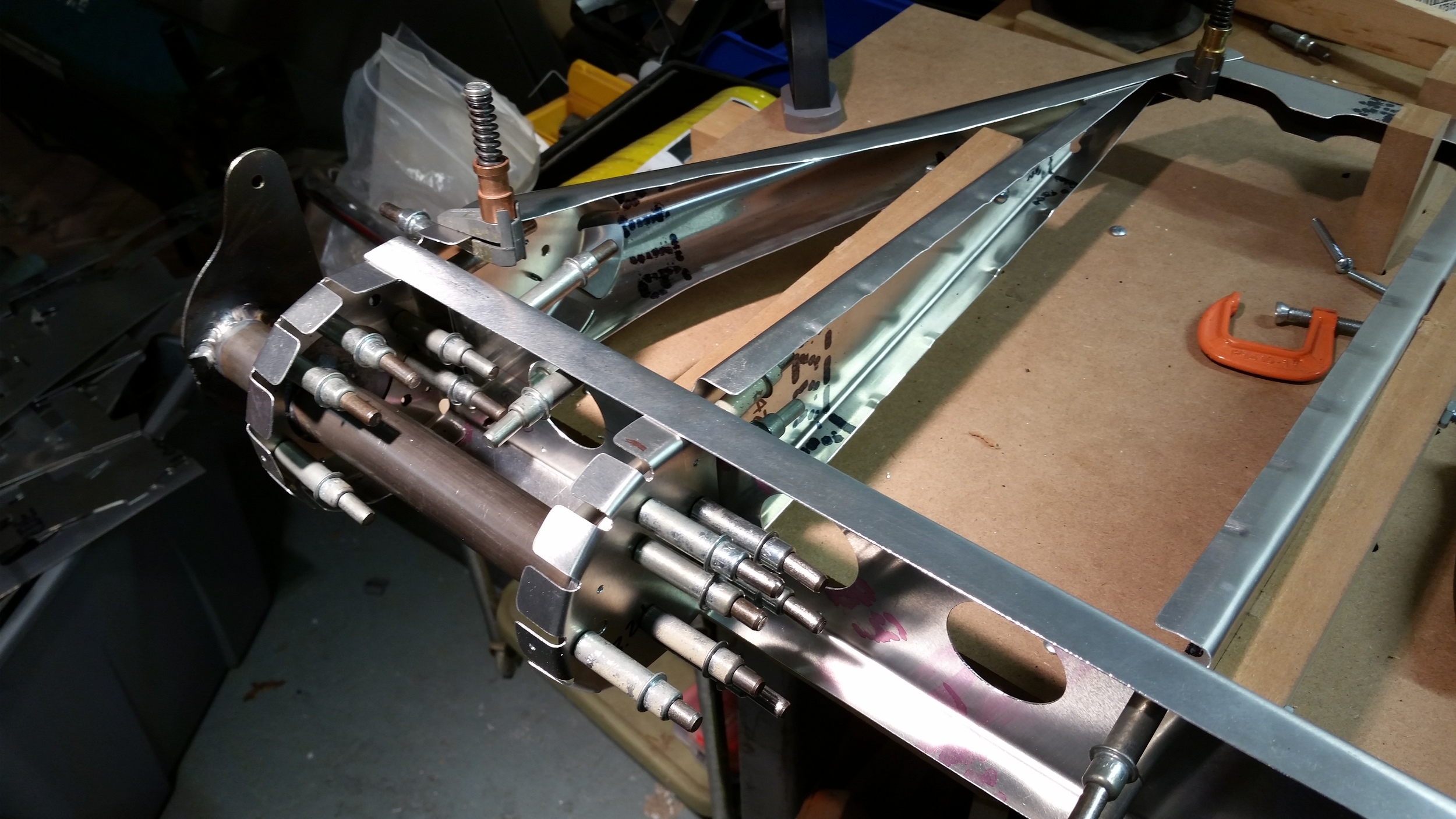
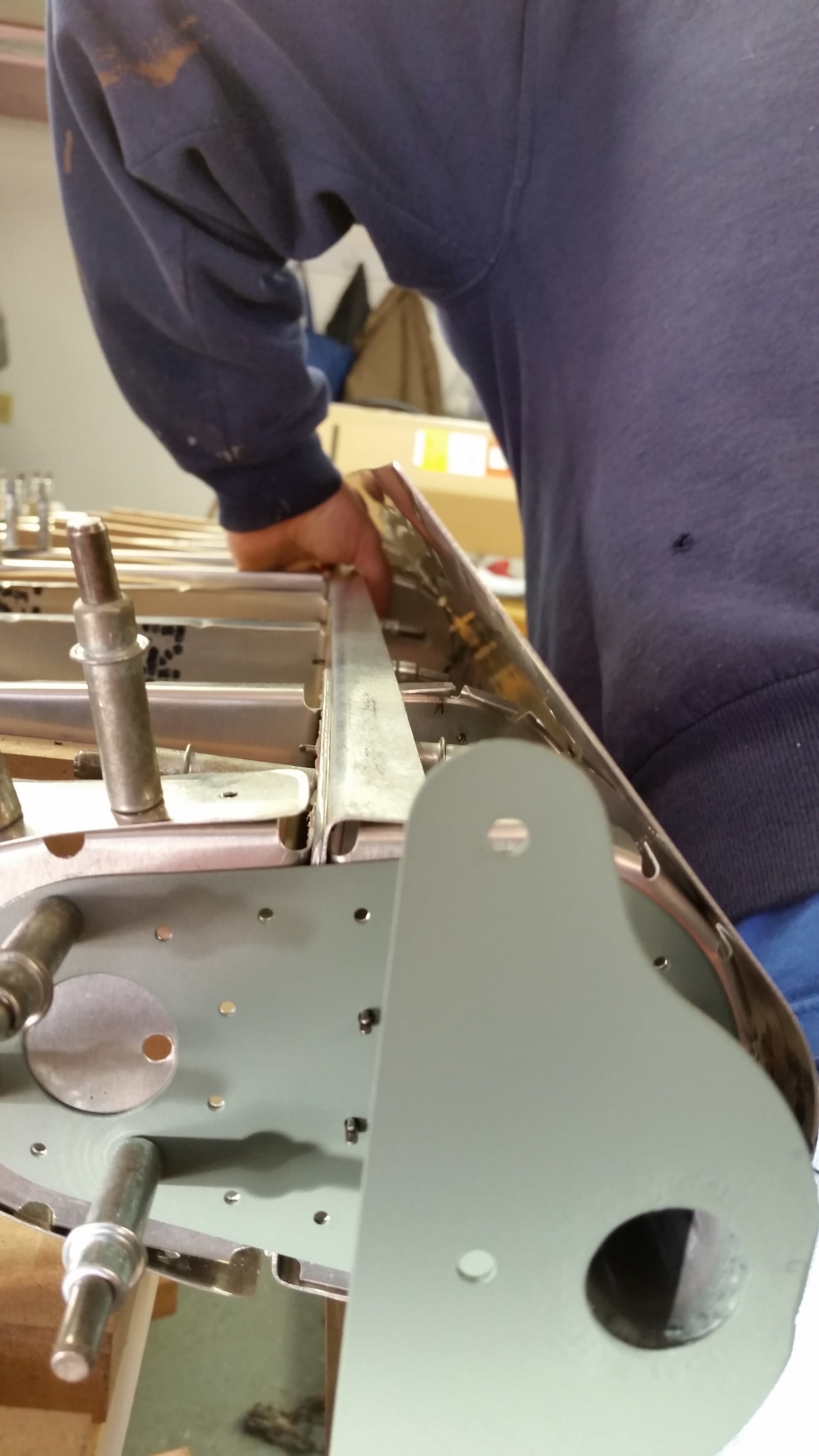
An important part of the Elevator, the attachment bracket to the control linkages. In our design, we're using a torque tube that attaches at two points into the leading edge. A welding fixture was slotted together and held everything in place through the various stages of welding. The resulting parts needed minimal work after being welded together to fit perfectly, and the results I think are pretty satisfactory.
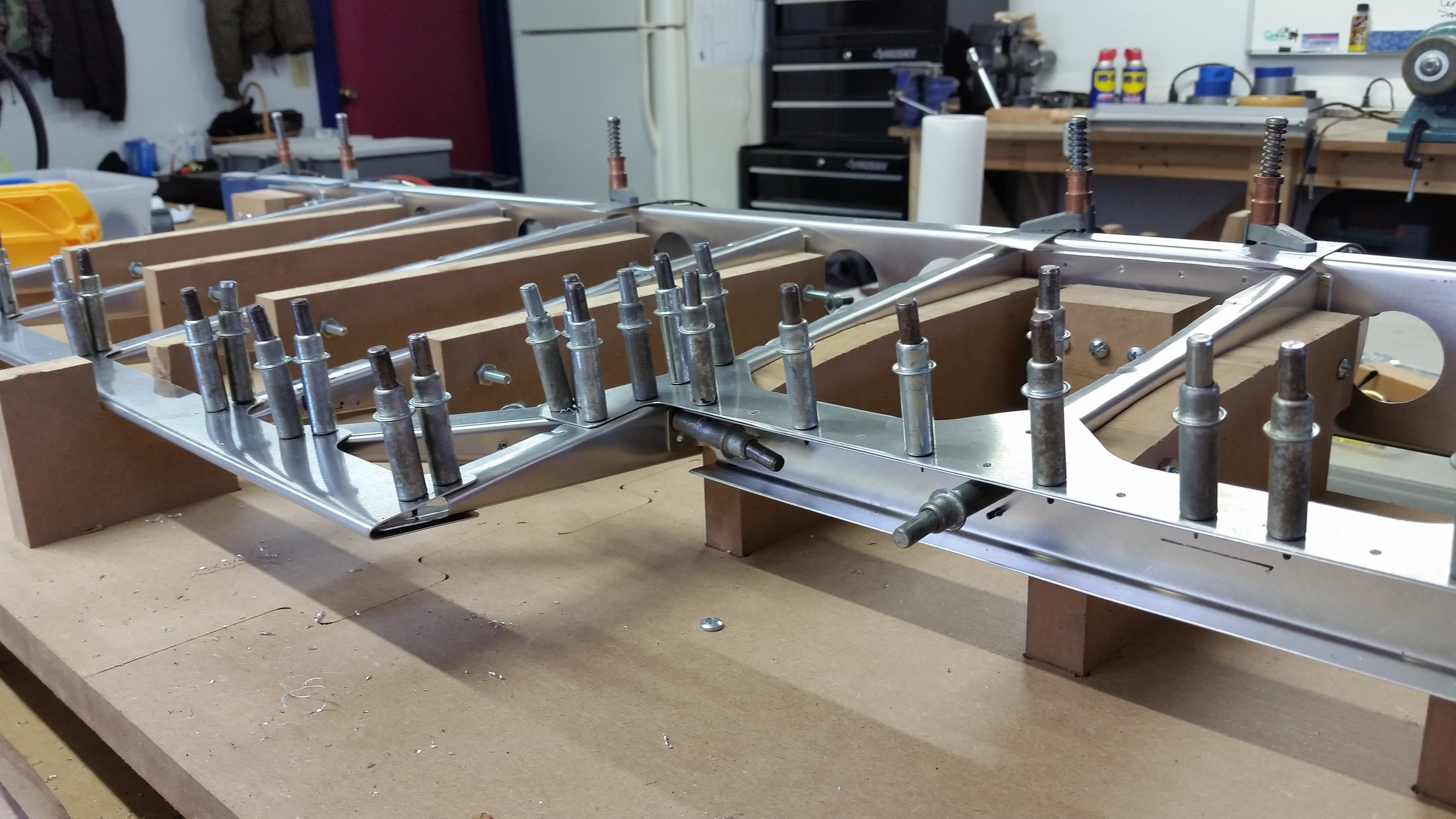
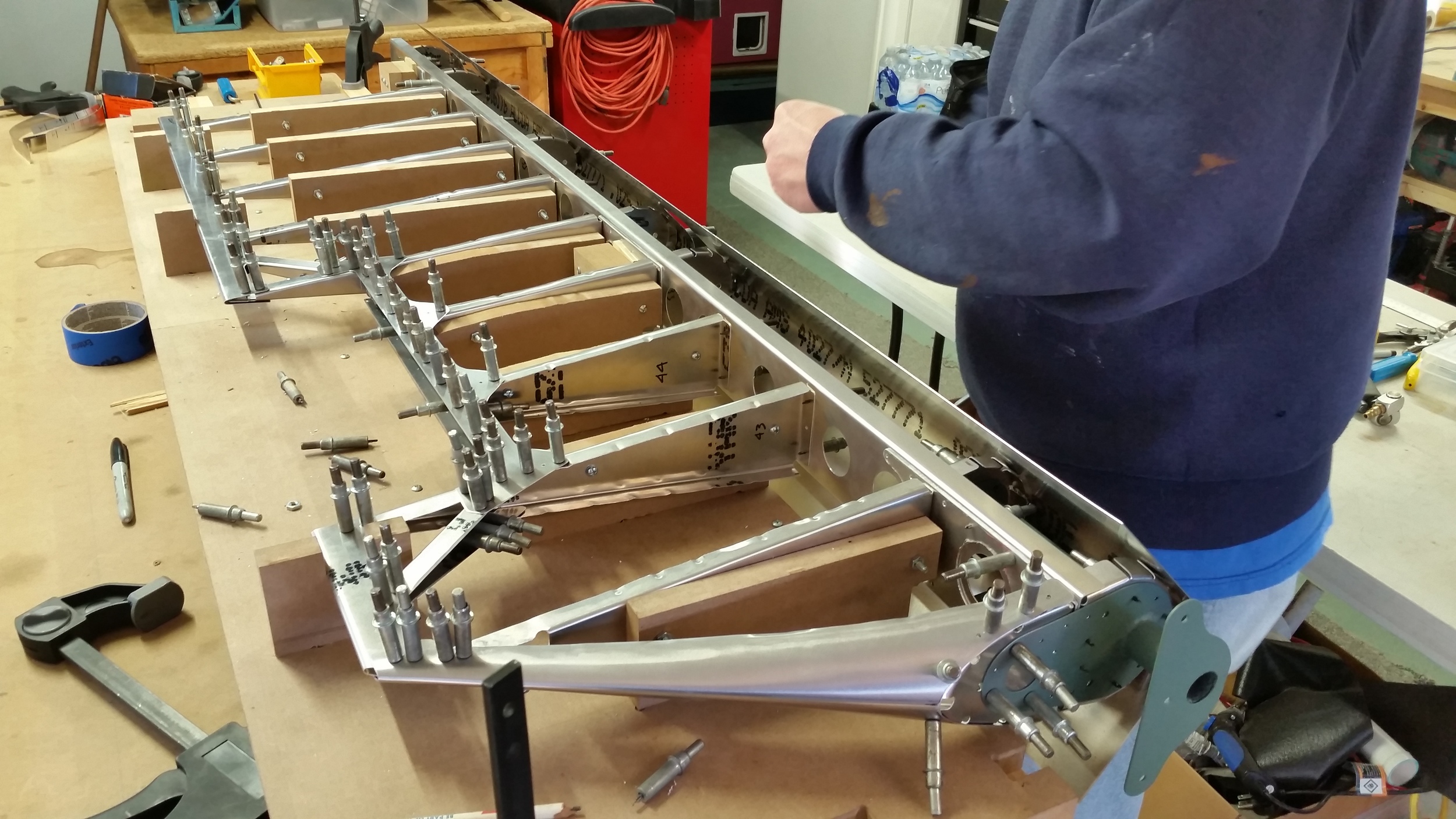
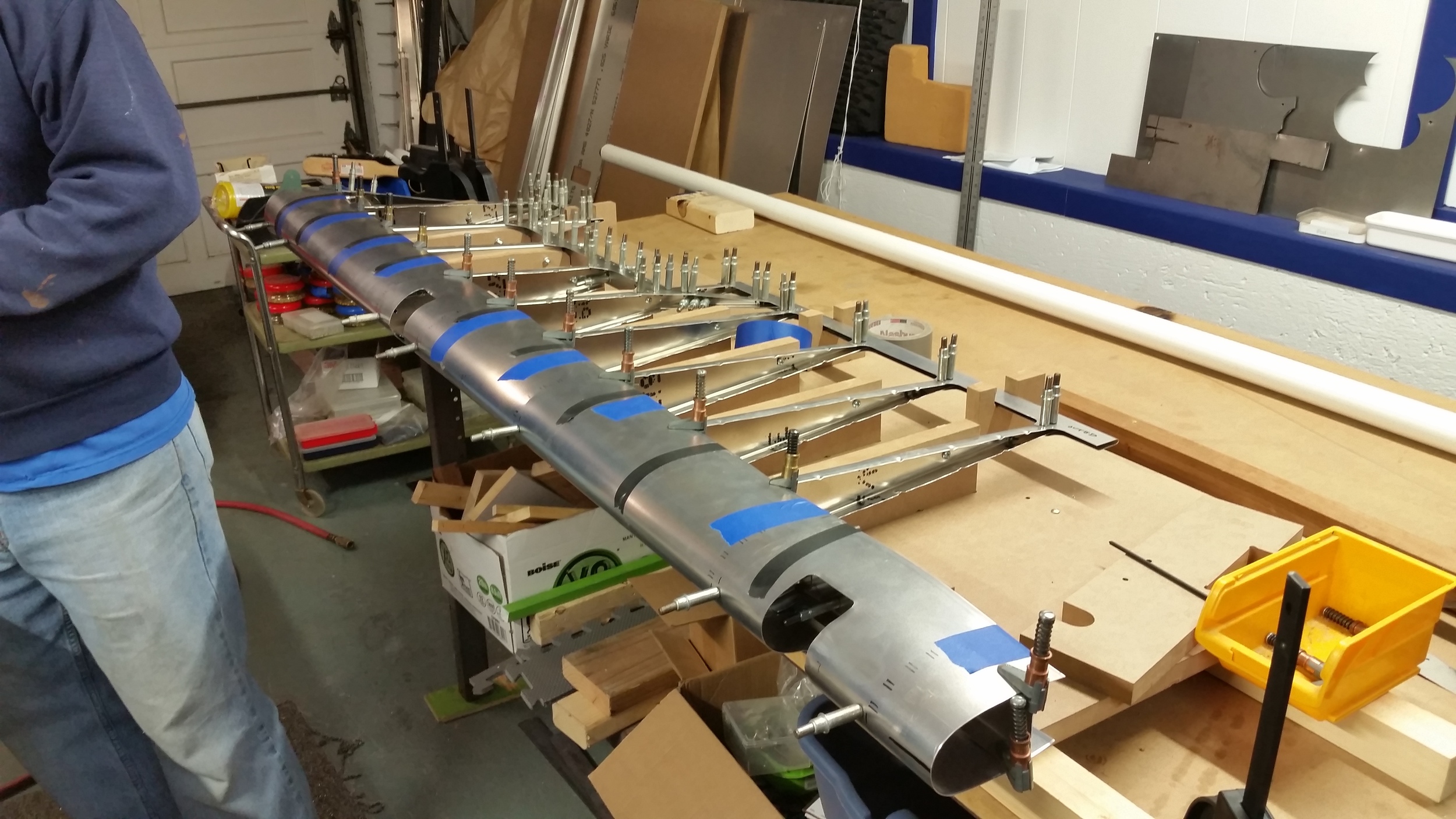
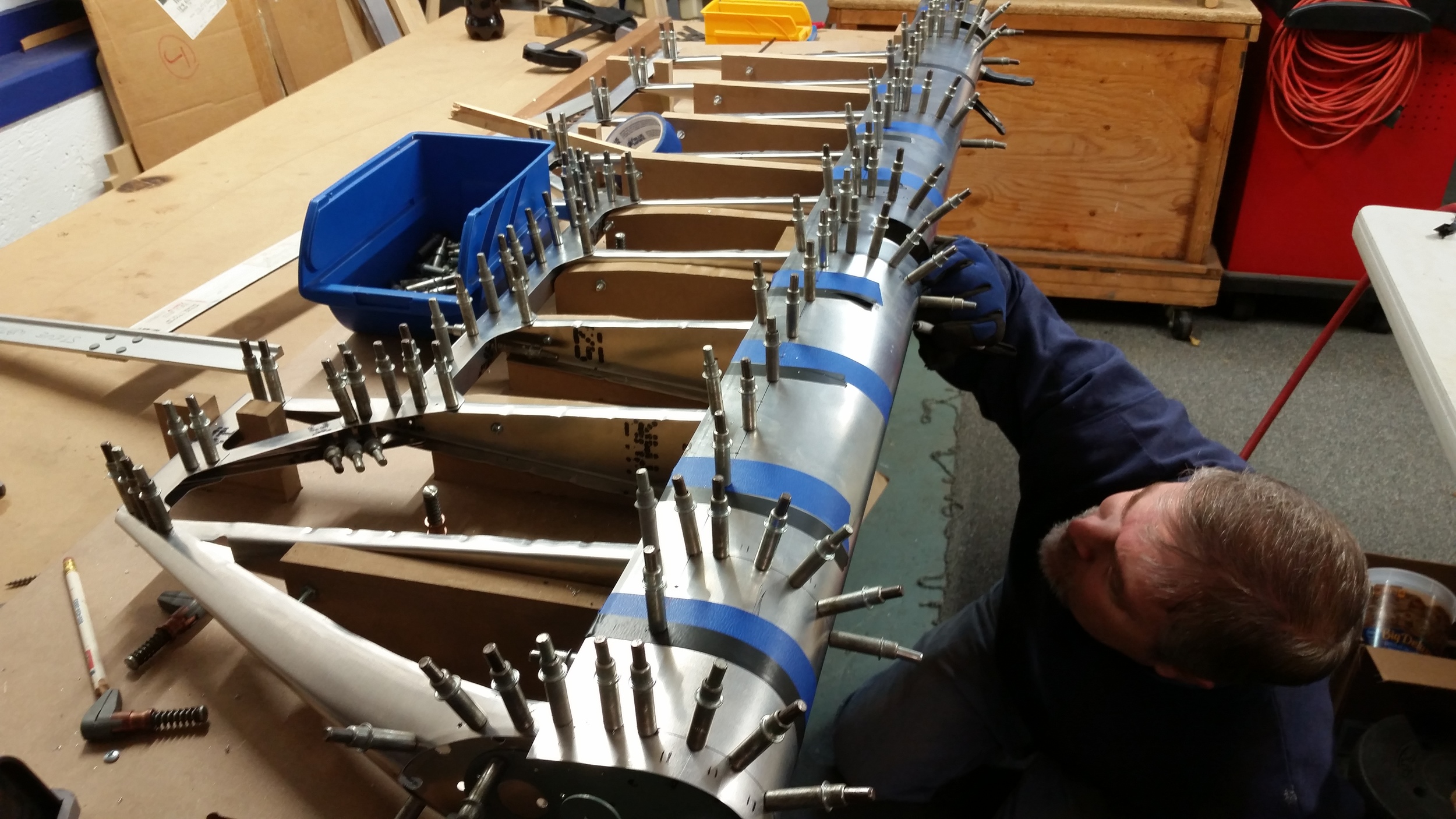
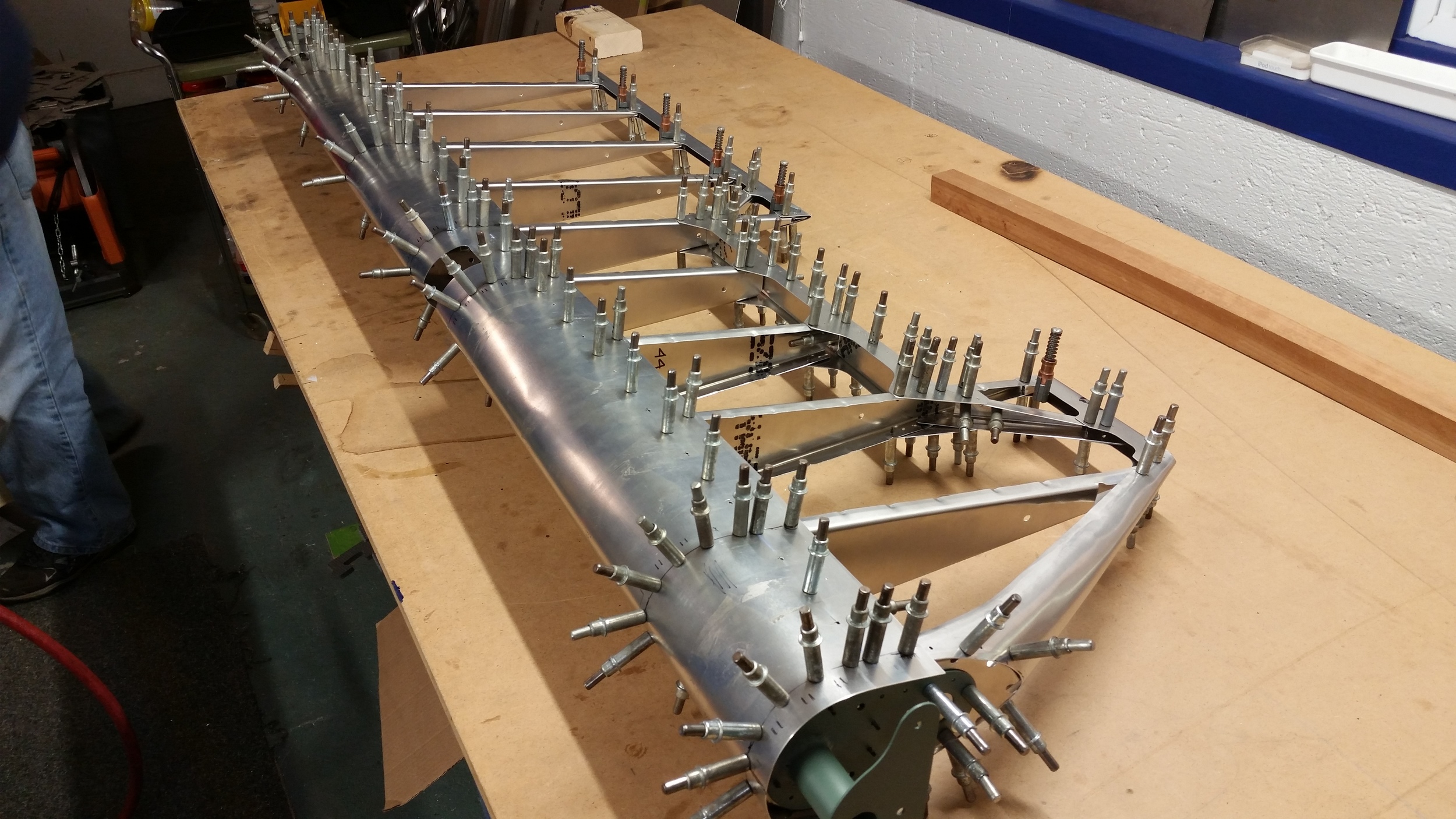
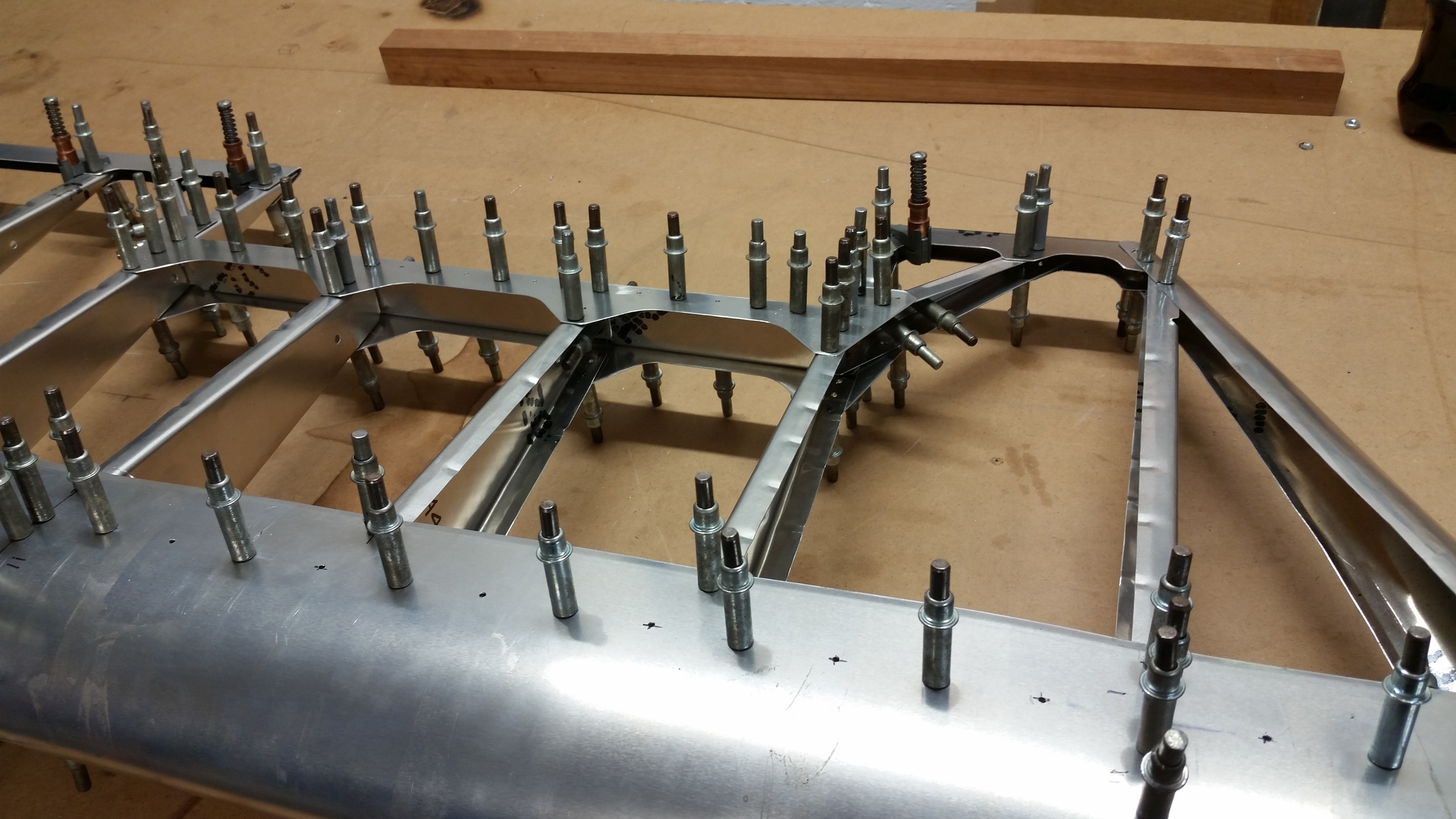
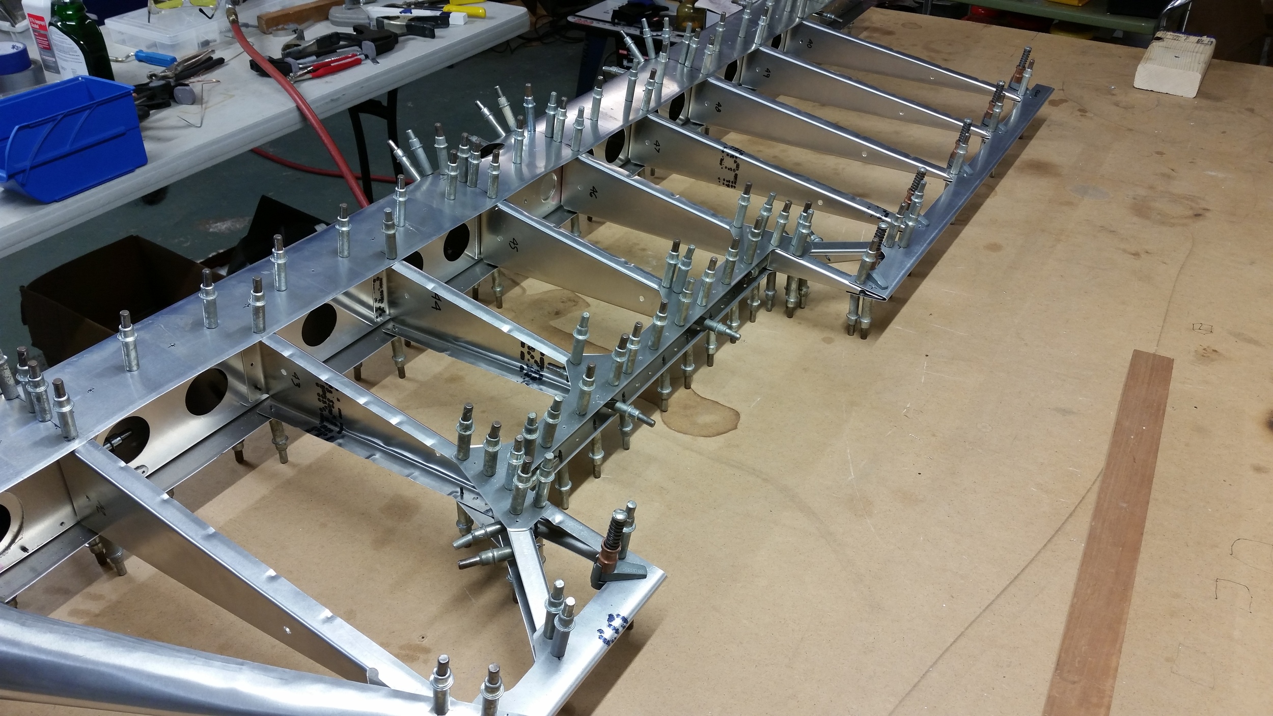
Everything was drilled and cleco'd to the spar. "Even though the pilot holes were aligned well, the holes all had to be upsized in-situ. Then came time to form the leading edge skin.
One of the challenges we're facing at the moment is a lack of a proper way to form leading edges on narrow skins such as on the control surfaces. As it is, we've had sufficient luck using pipe and clamps and a bit of brute force, but as we progress in the future I'd love to see a more effective and repeatable skin bender that can form ideal leading edges. At any rate, we were able to pre-bend the sheet sufficiently and then strap it tight to the ribs for drilling. It was some work but the final result is nice.
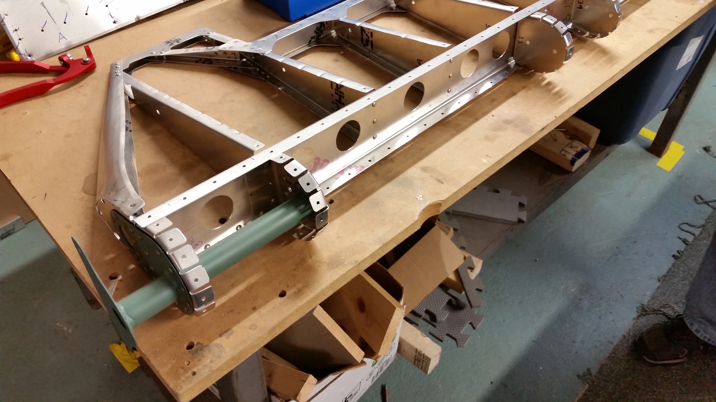
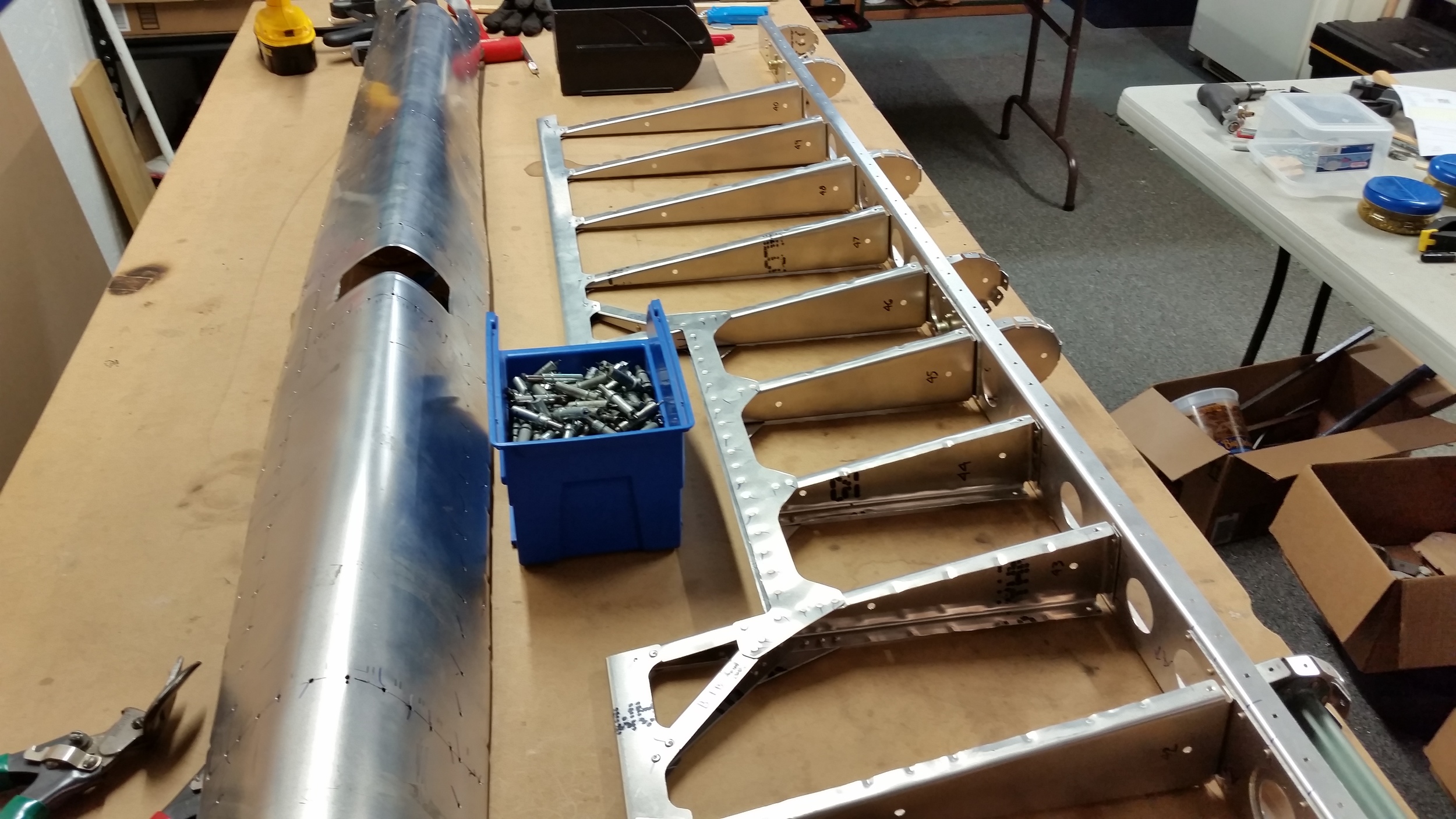
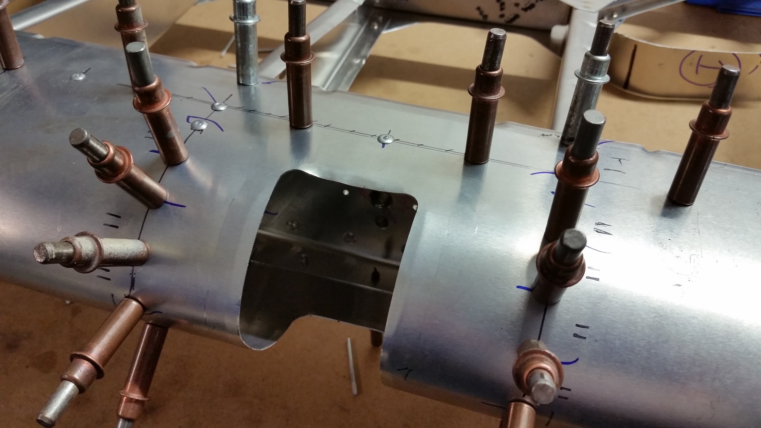
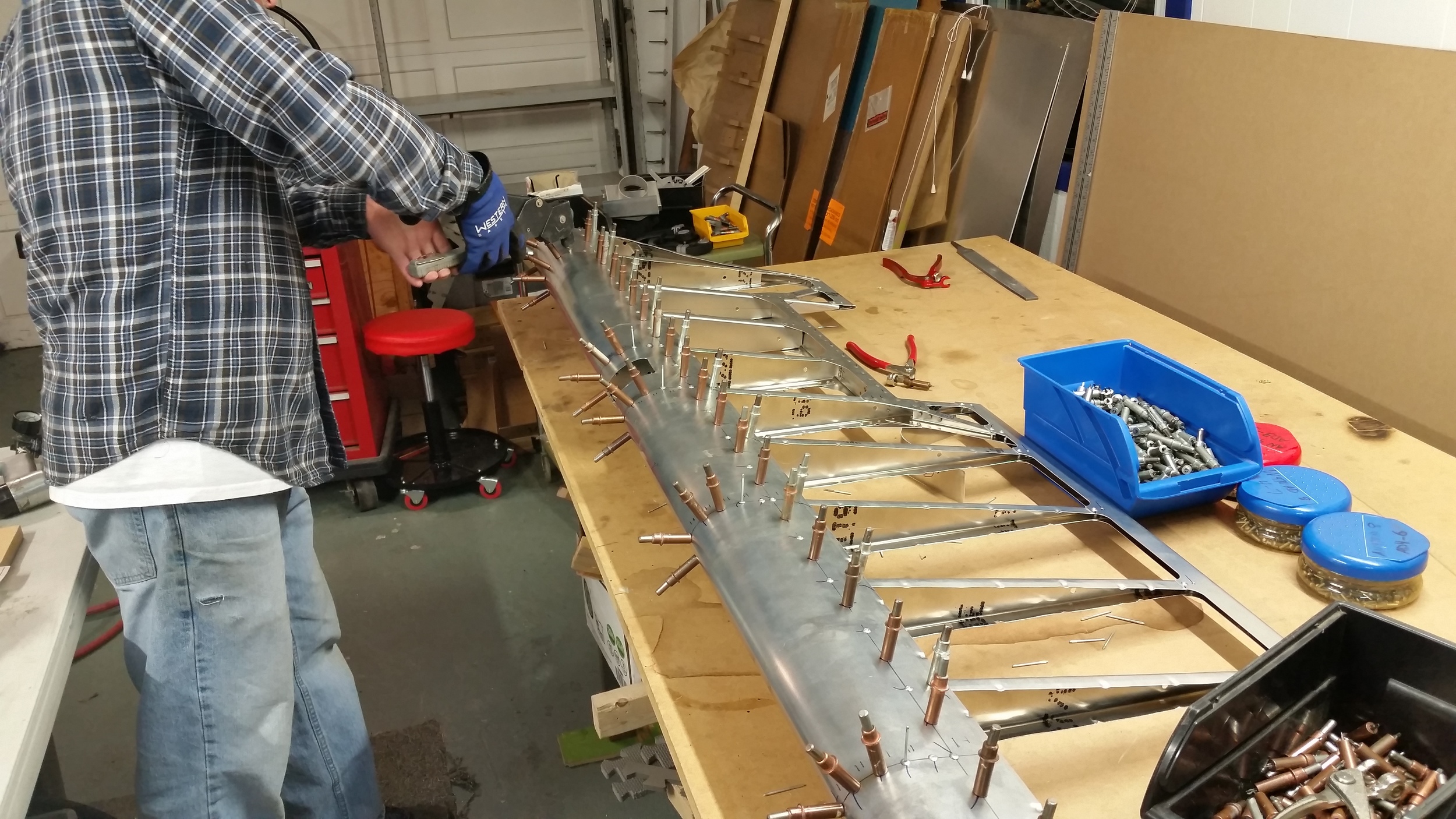
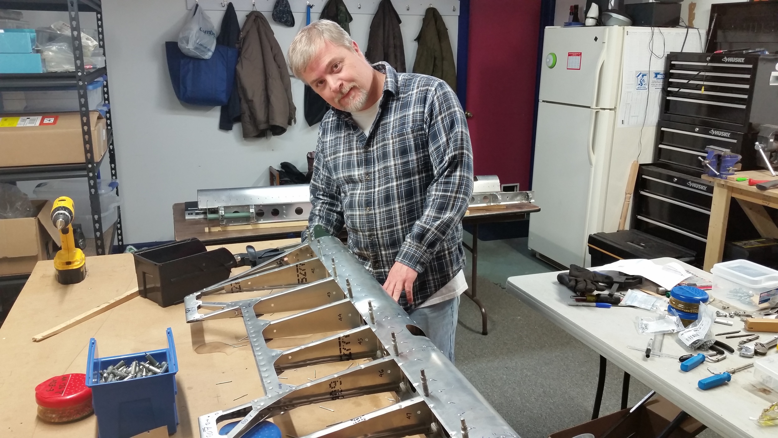
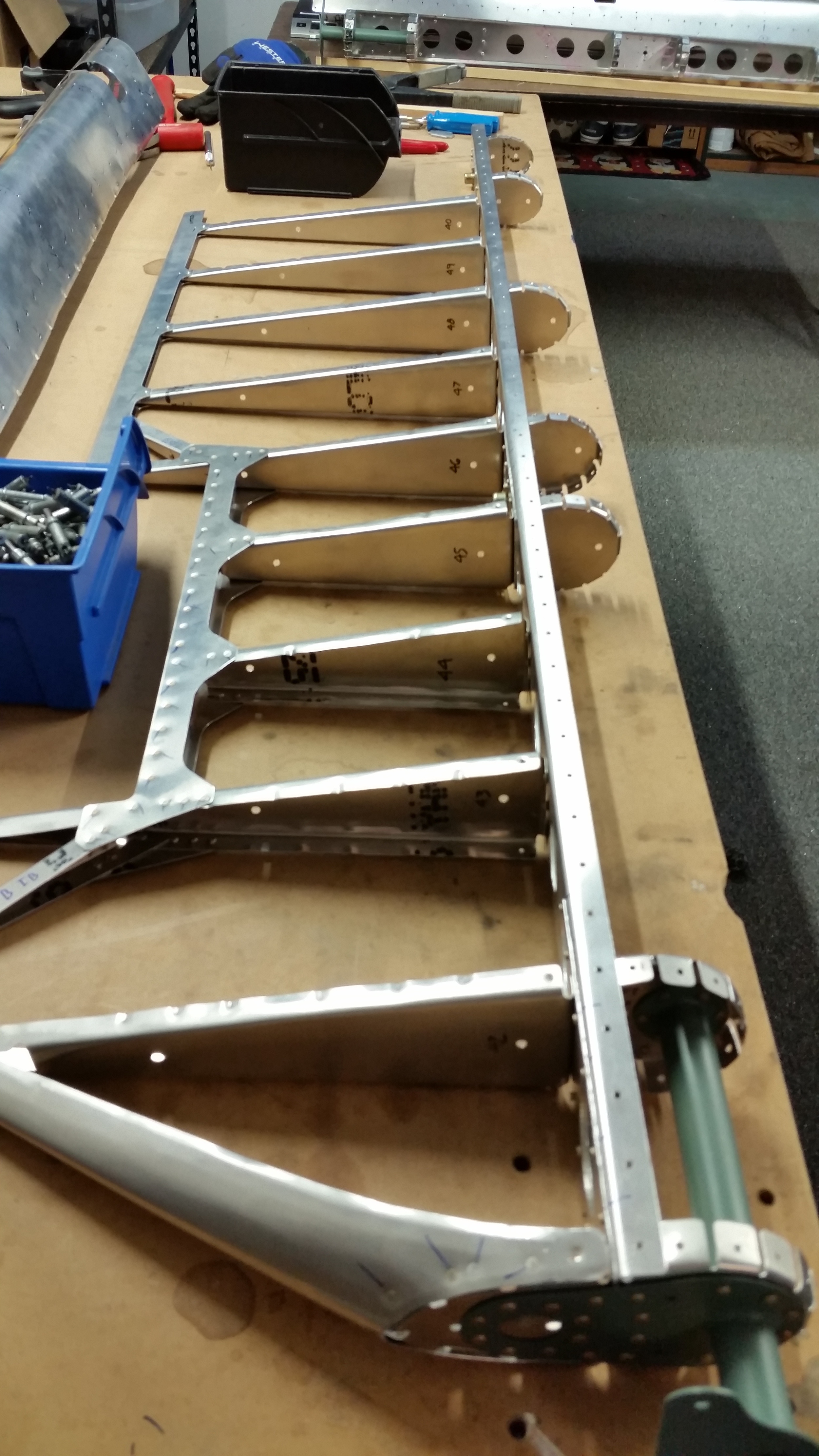
With all holes drilled and parts prepped, the only thing left was to rivet everything together. Order of operations is very important when riveting these parts as there are areas that cannot be accessed if things are not done in the right sequence. In this case, the ribs were first attached to the spars, then the torque tube was riveted to its supports. With that installed it was time to attach the trailing edges and the trim-tab spar with rivets, with the leading edge skin being last.
A manual rivet puller was used for the first elevator because it was on hand. The second one, we went and got a pneumatic puller.
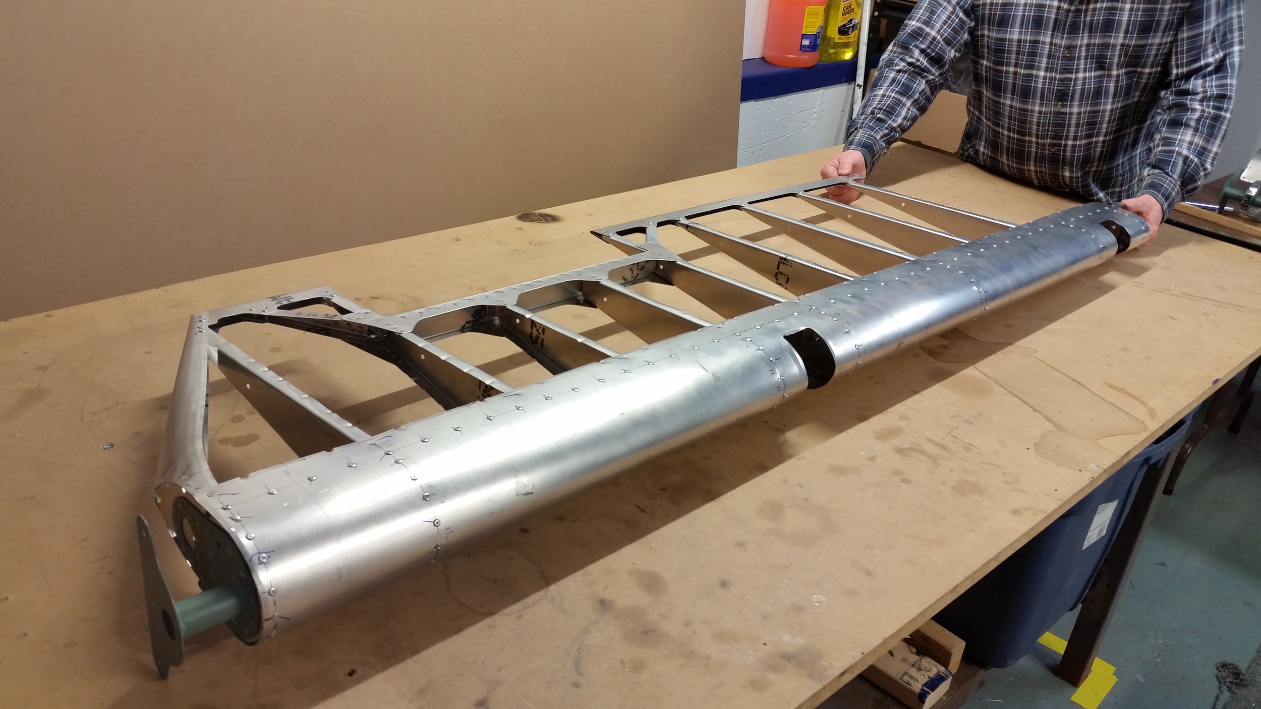

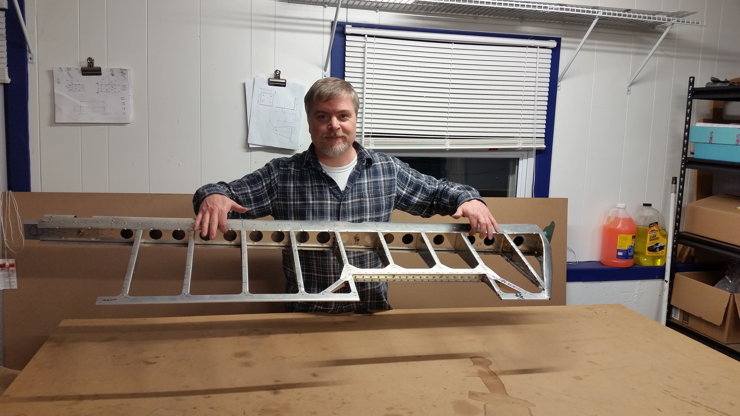

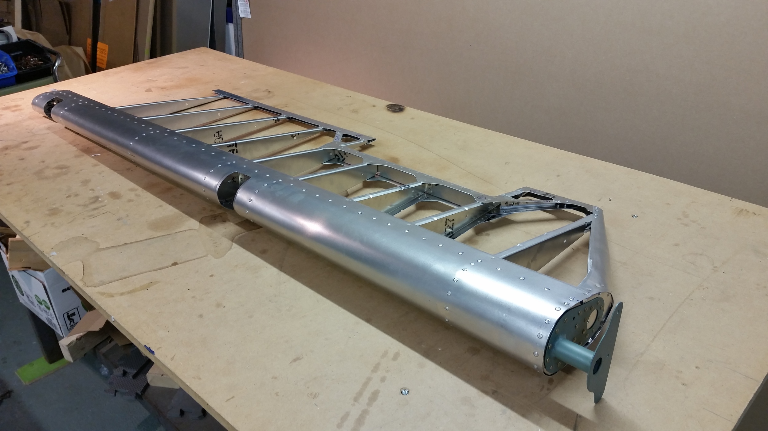

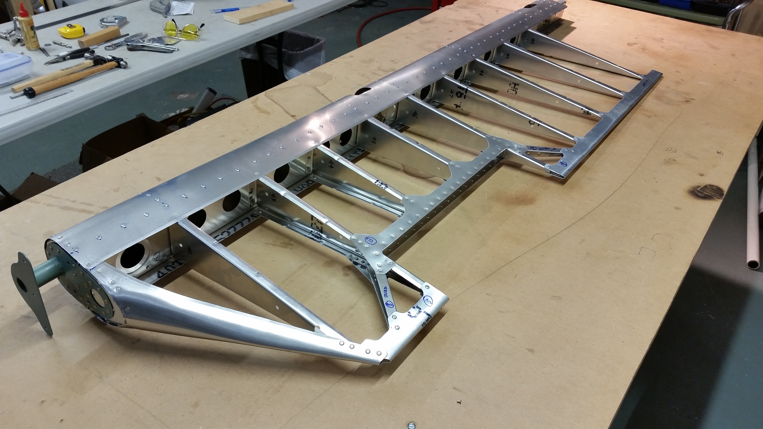

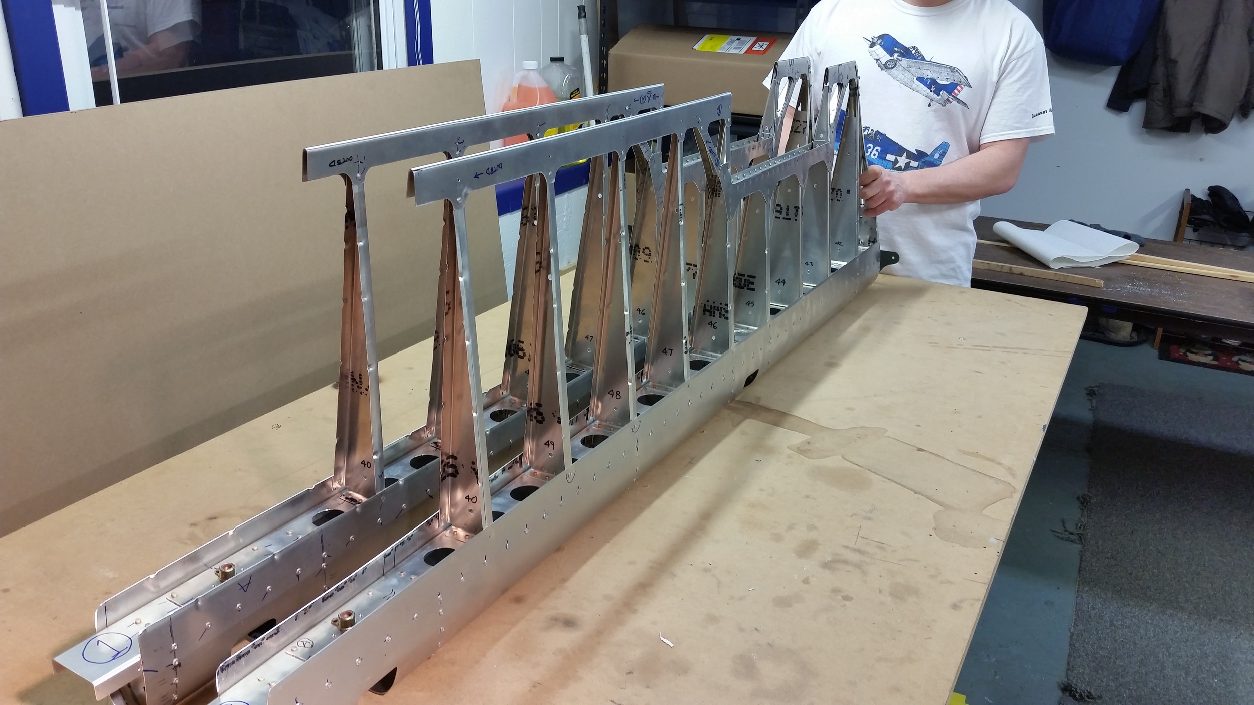

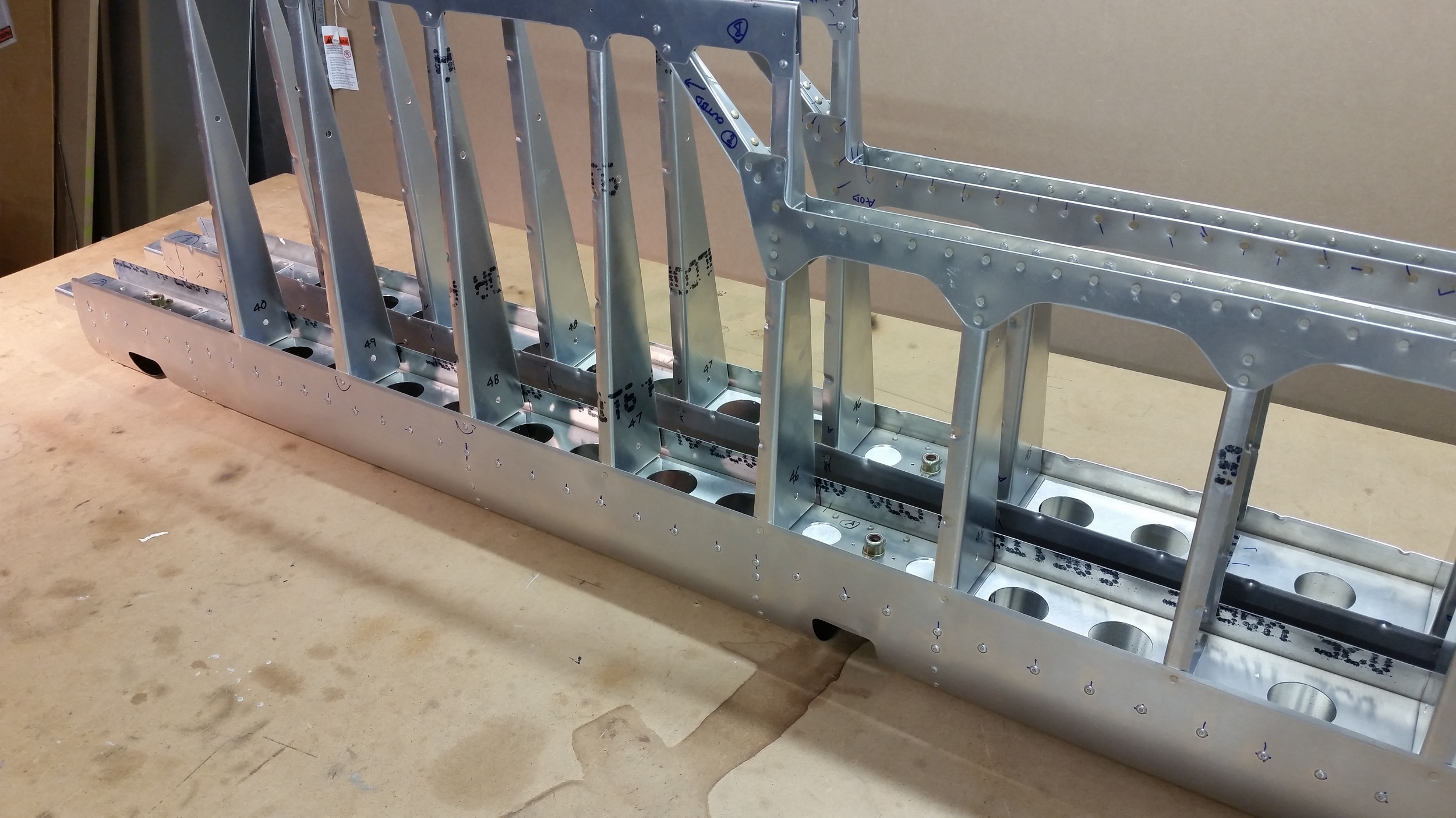

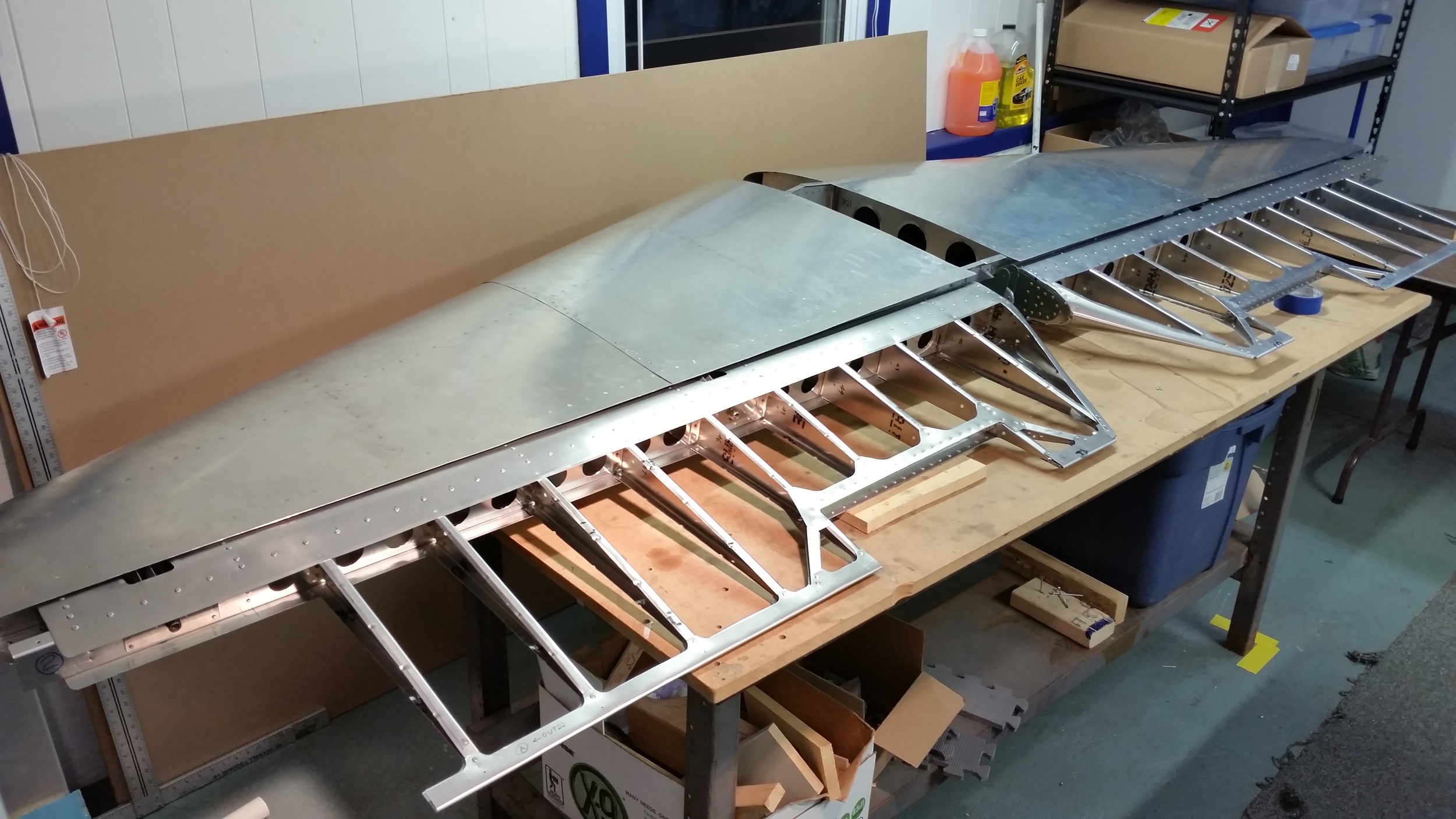
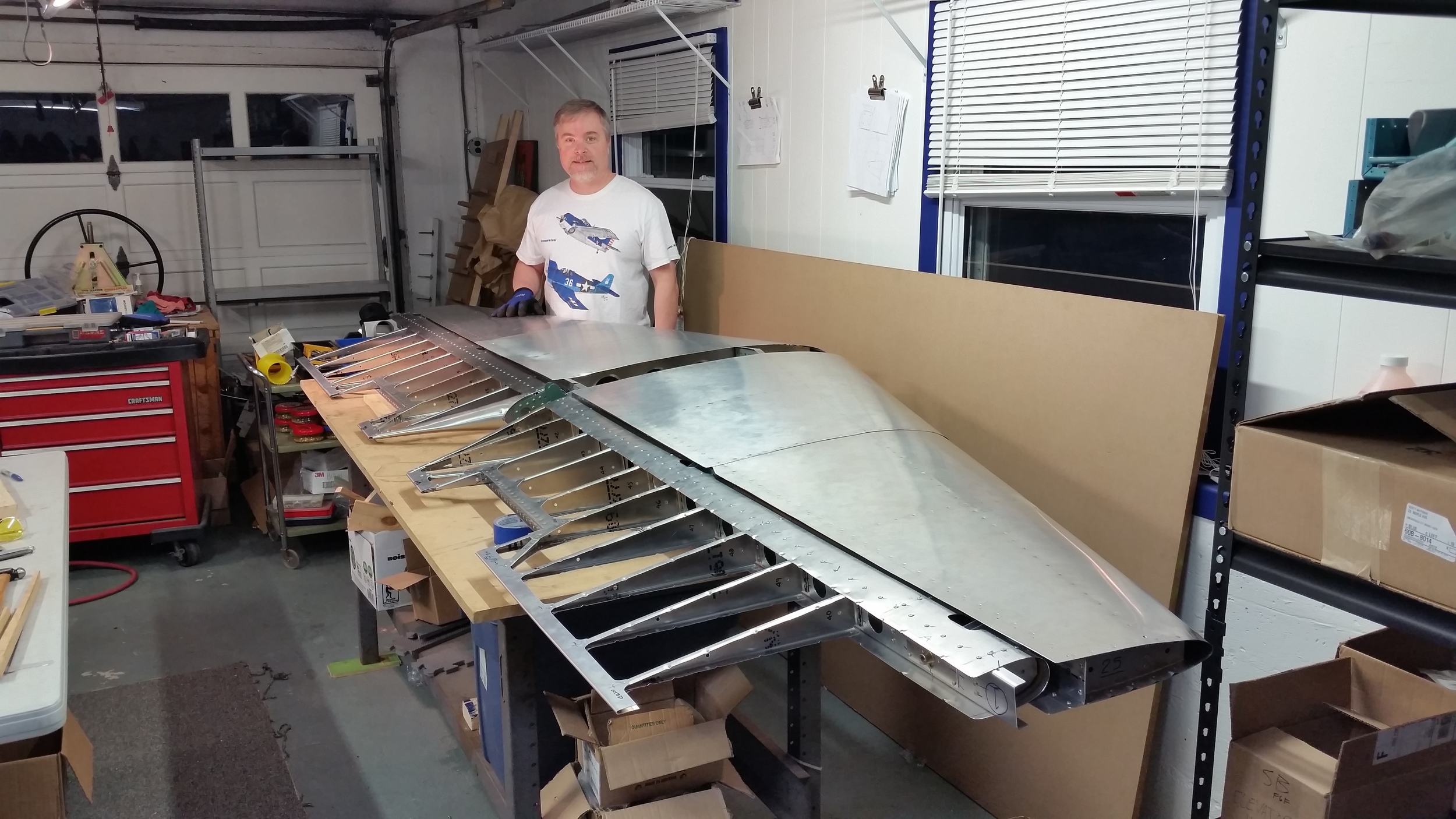

The two elevators were finished, for now, with the attachment of the leading edges. There is more to do however!
In the future we will have to cover the elevators and other control surfaces with a fabric; I like the idea of using Oratex material. Before that, we need to add tips to the elevator, which may be formed aluminum, but may just be composite forming parts. In addition on one elevator we will have to add the adapter plate and baseplate for the Trim Tab servo, as well as hinges for the trim-tabs. At that stage, we will drill through a few of the rivets on the trailing edges and add the hinges over top of the fabric to keep things clean.
So that's the Elevators, the first parts we have built with the intent of flying them on the first Hellcat. Work has already begun on the Rudder and other components, and as those reach their milestones, expect more updates.
-SSW Out

