ScaleBirds

ScaleBirds, Home of the 63% Scale Hellcat replica kitplane project.

Steady as She Goes

It is about time we got to another blog entry. As always - way late. The Covid virus has had its impacts on our project - delays with shipping and vendors, etc... Gladly, no one on our team has contracted the virus - that we know of. It has prevented the whole team from getting together to work on the project. Mostly it’s just Scott and myself working on the physical parts. Slow going, but progress has been made. I am working the day job from home - super unusual for defense work. It gives me about an extra hour a day to work on the project. I’ll take it!

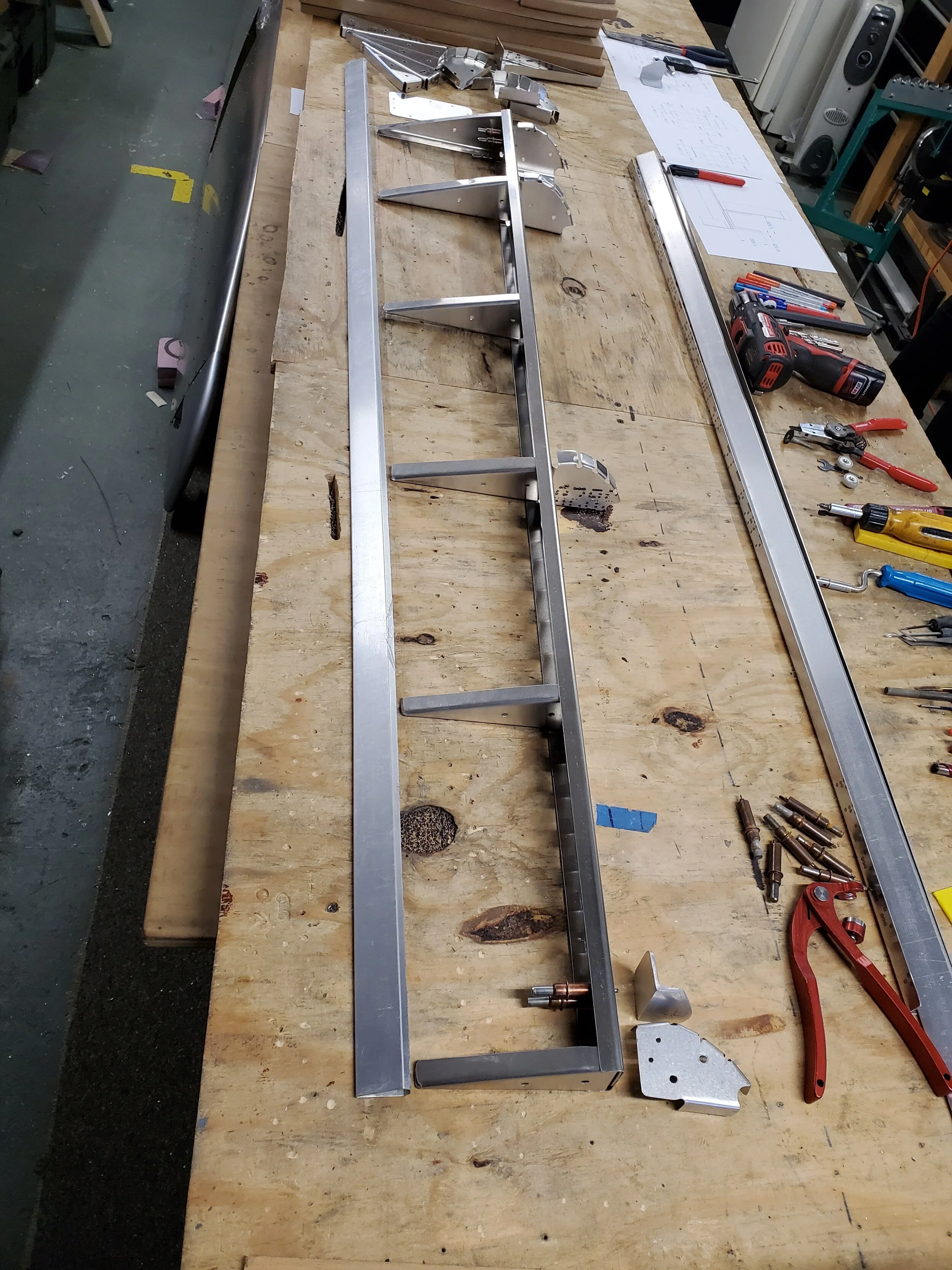
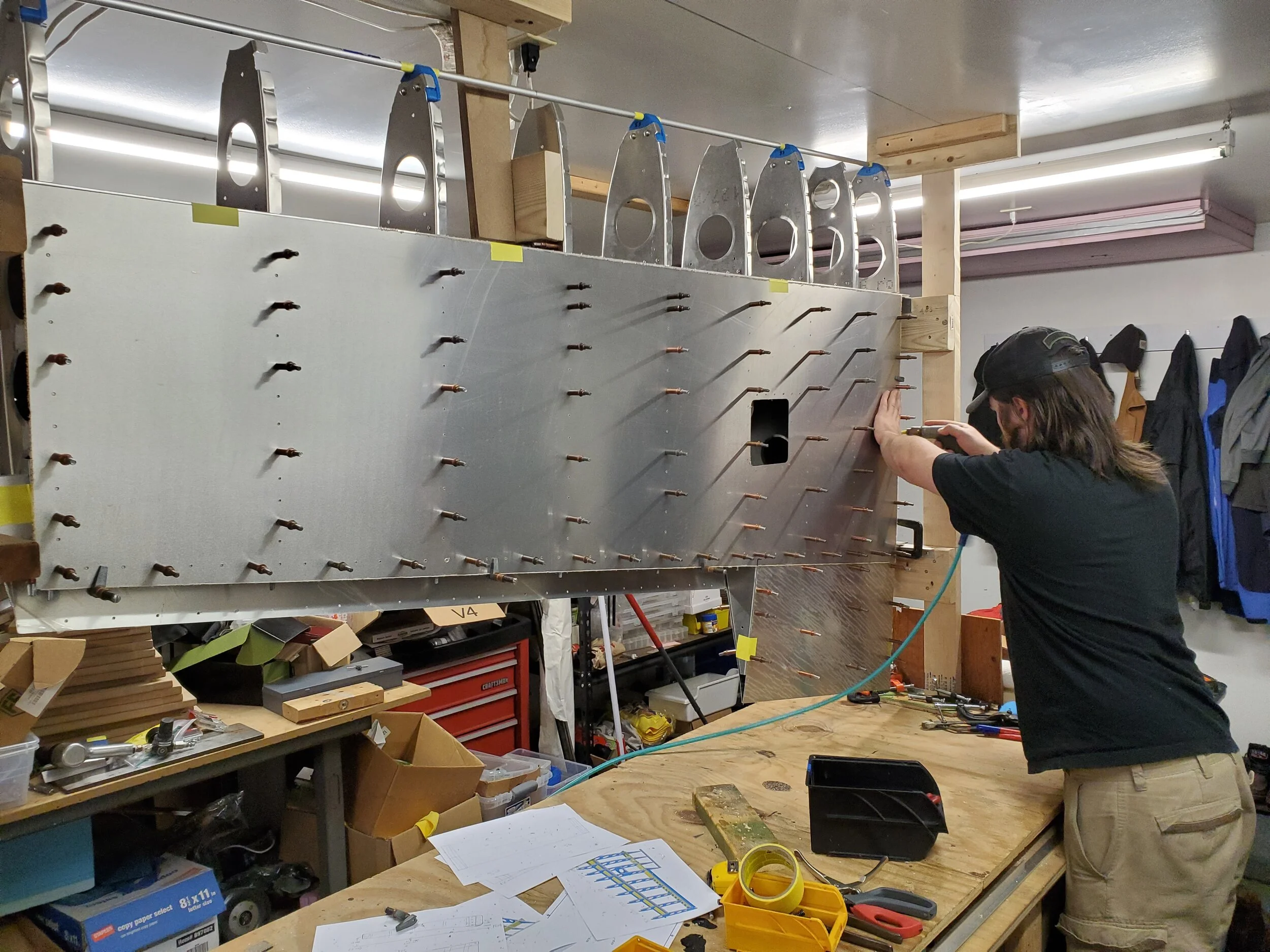
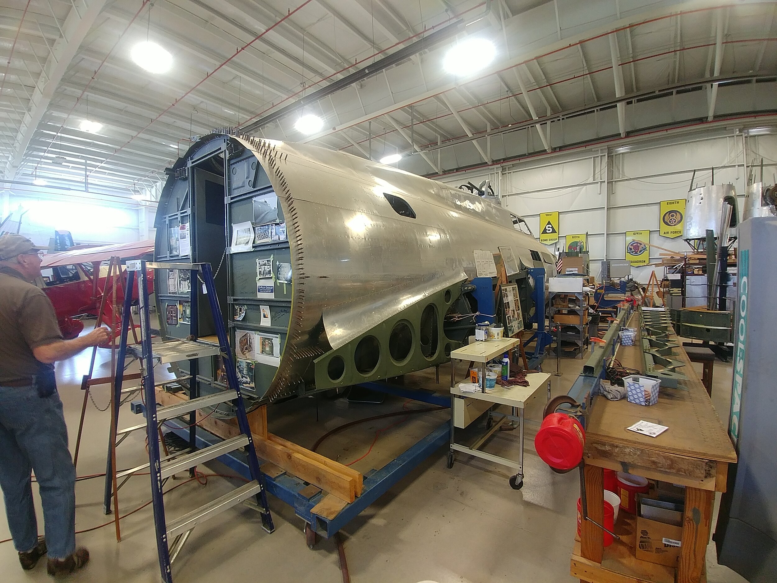
After building the rack for the fuselage, we removed the wing center-section and landing gear. Then, one wing half at a time, we mated the outboard wing to that sides’ inboard wing panel. They mated-up almost perfectly - thanks to CAD and CNC mfg. We only needed to remove a little bit of spar web that we left long for some reason - we don’t think of everything first time around! The spar caps and mounting brackets fit together like a glove. That allowed us to finish the trailing edges of the outboard wing and the aileron - aligning them with the inboard panel’s trailing edge. We started with the port - left - wing first. after finishing the aileron, we went into working on the wing tip.

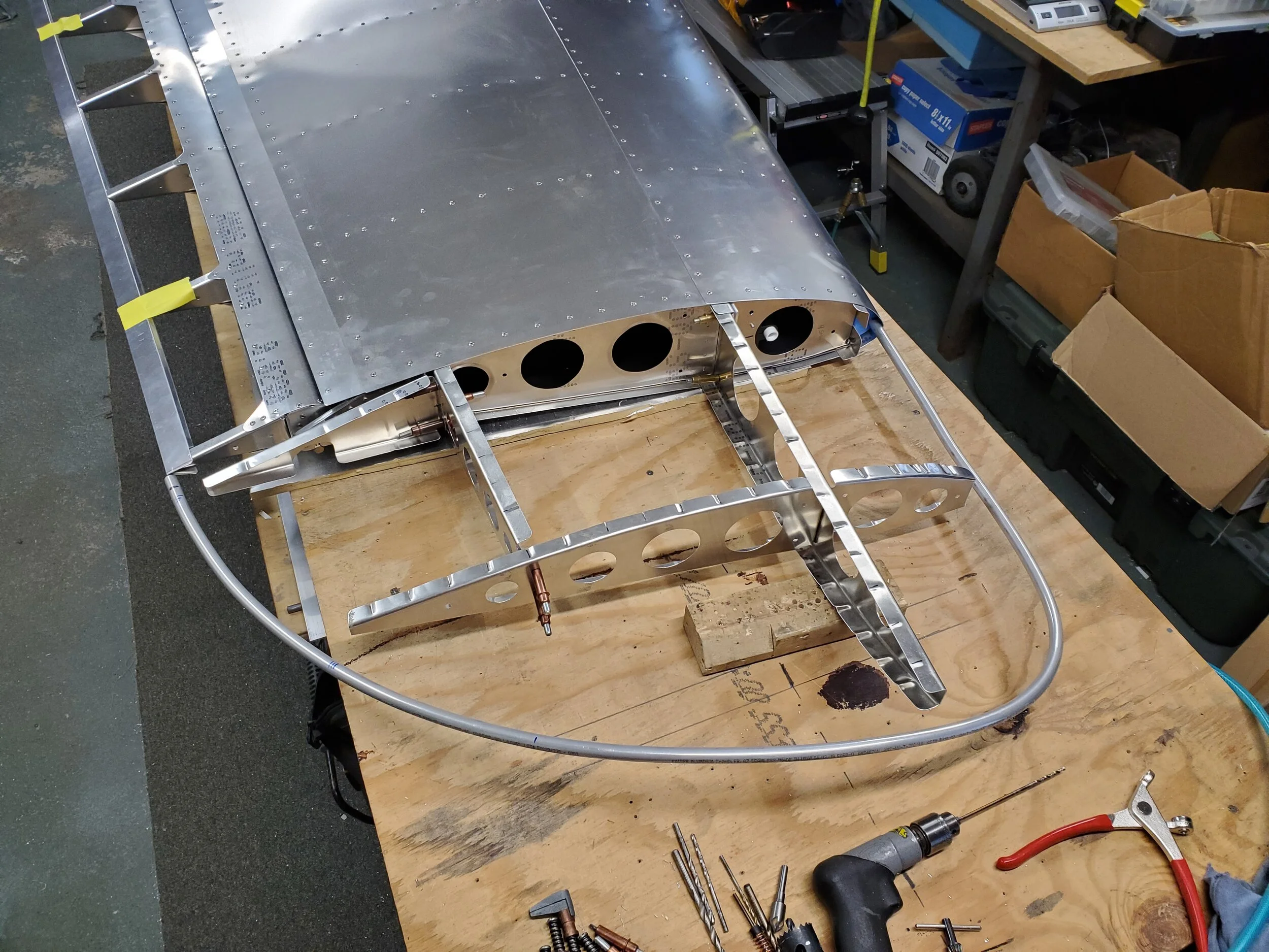
The wing tips were originally going to be composite and just bolted and riveted on. Easy peezy! Well, problem is we were going to be a long time getting them - our buddy switched to making masks and face shields for first responders. Good cause for sure! But it is another major delay we are dealing with. So we thought about it. The real one is metal. Can we do it? After studying the real P-36 wing tip design and the P-40B that we had close-up images of, we decided that we could do a decent job of making it from metal - if we can english wheel a small panel on the bottom leading edge. Another way would be to hydro-form the piece. Turns-out, Curtiss designed the wing tip shape to work with the airfoil - almost all of the top surface and more than half the bottom surface line up with a 3D shaped tip bow and readily lay right down onto the bow. We just had to round the outboard edge to lay against the bow and rivet in place. Hand pounding along a curved steal mandrel worked well. To do the very curved bottom leading edge piece, we purchased a small, vice mounted english wheel and spent some time playing with shaping scraps. Well, it is not easy, but we taught ourselves to wheel soft aluminum sheet. YouTube videos helped. Much better equipment would also help. This was relatively inexpensive and small - it does not take up valuable floor space in our shop - we don’t have any to spare! You get what you pay for though - its much rougher wheel paths, but it did work well enough I think for sanding and painting the tips - not quite good enough for polished metal finishes.

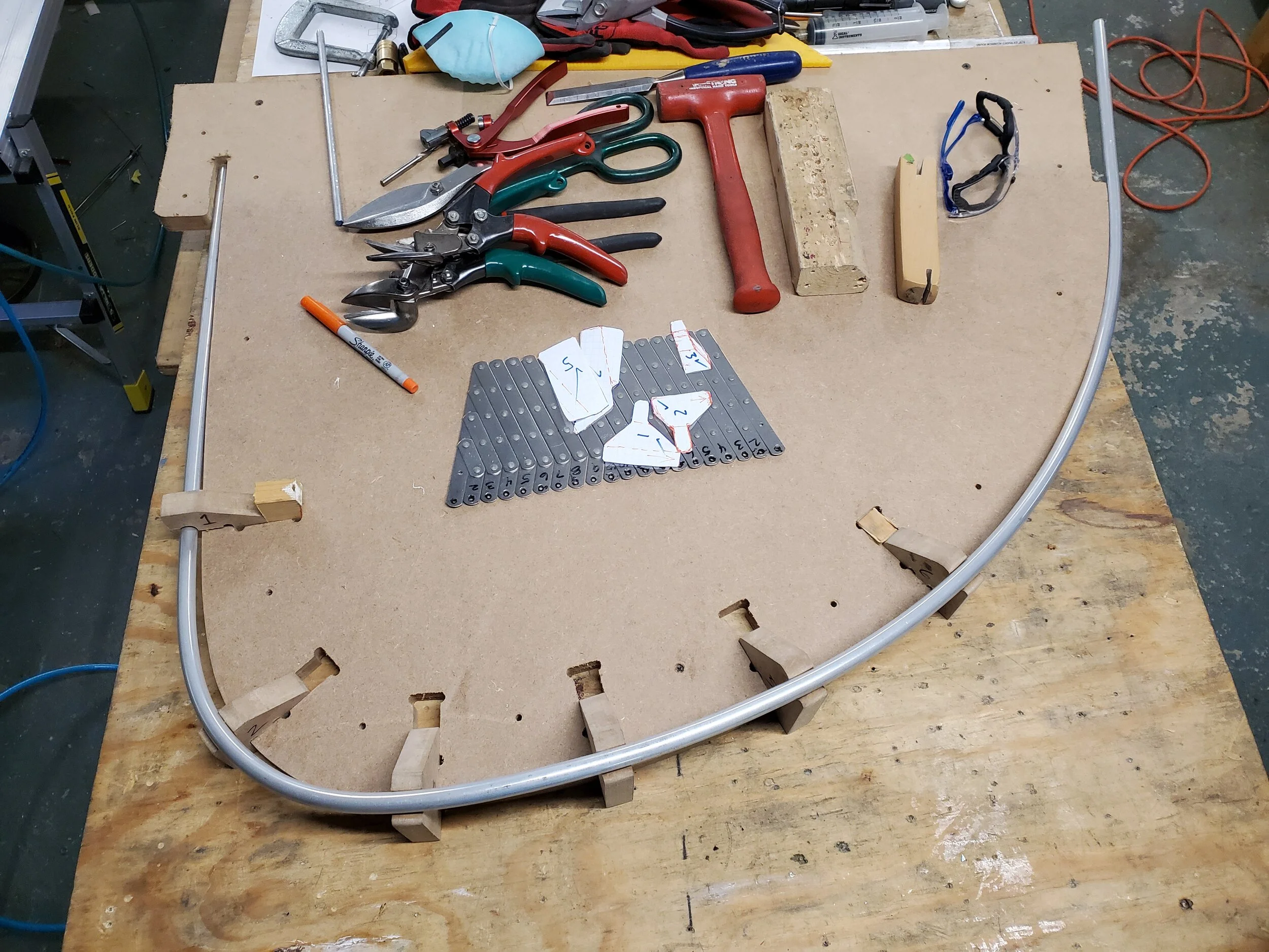
We fabricated the wing tip bows from 3/8 tubing and bending around a wood form. Then added 3D shape to it with wood jigs at various stations along the bow. Hand forming the bow to shape. In and out of this fixture a bunch of times before having it sit perfectly in place. Then we fitted the ribs and short spars parts that make up a support frame for the tip. That’s when we worked the skins and drilled, riveted them in place.

After fitting the last of the left wing tip skins, Scott wanted to make spring retractable tie-down rings - per Curtiss. He designed them to be very similar to the original, but easy to fabricate with our equipment. He also had to design a welding and milling fixture that worked really well. I welded the rings to the print and Scott cleaned them up and added holes on the mill. Then he cut the aluminum mounting bracket on the mill and installed everything. I think they turned-out awesome!

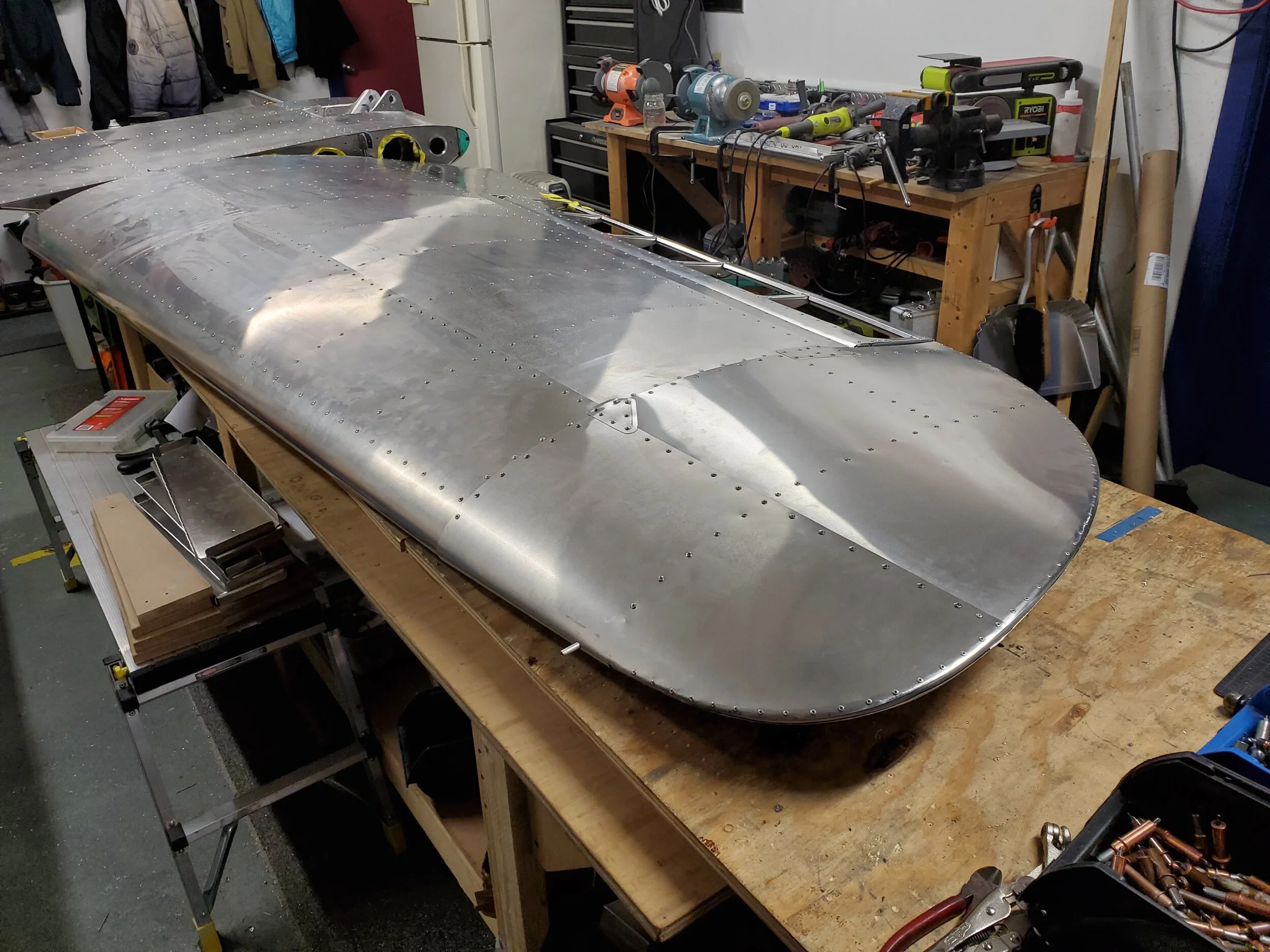
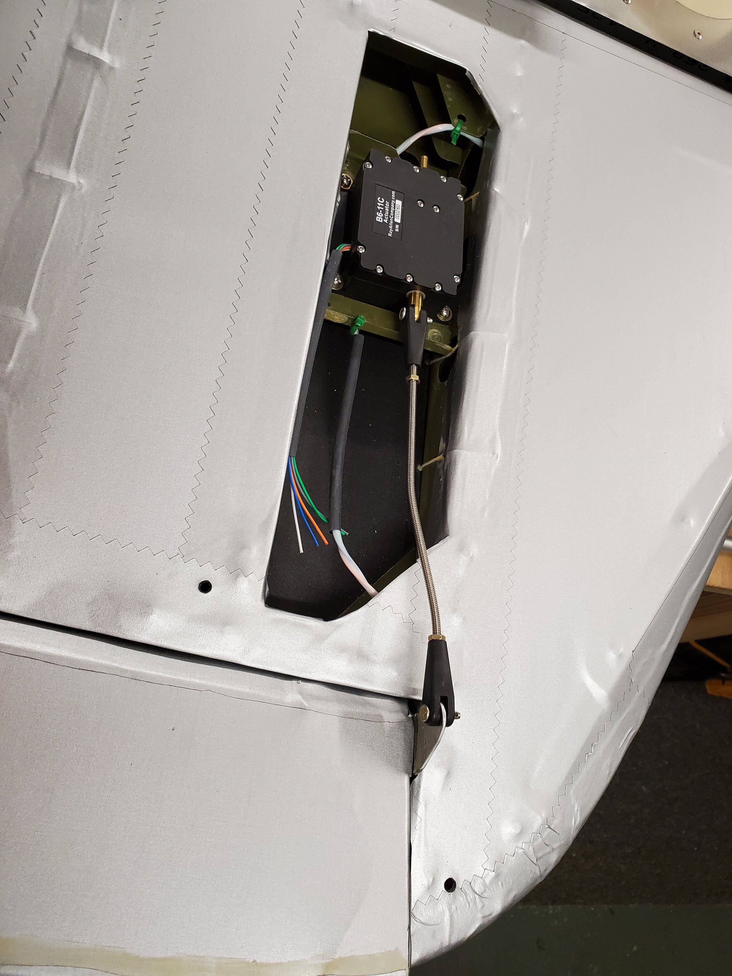
The left wing also gets the pitot mast and head. On most of the early WW2 aircraft, the pitot head was this large spear with a shark fin. We looked at machining it - very serious machining and decided against it. 3D printing was a good option. Scott’s friend is now president of a 3D printing company doing amazing parts for medical and defense customers. He printed our design up on a state of the art printer. It came out looking like it was cast. Just the slightest surface grain - like a #2 mold surface. It’s dark grey plastic resin but can be painted. I fabricated the mount that holds the mast and head to the leading edge. Scott made a bulkhead mount for the 1/4” aluminum tube to pass through the spar web where we wanted it to be. After installing the mount, we could close up the wing tip for good. Each wing tip has a generous access panel for getting to wiring and pitot components. So then we riveted the skins on. Wing done! I think it came out awesome for not being experienced metal craftsmen. And looking at the pictures, the originals were not perfect. Today, the restoration shops are paid millions and make everything perfect and then polished or gloss painted. Back in the day, they were slamming them out as fast as they could.

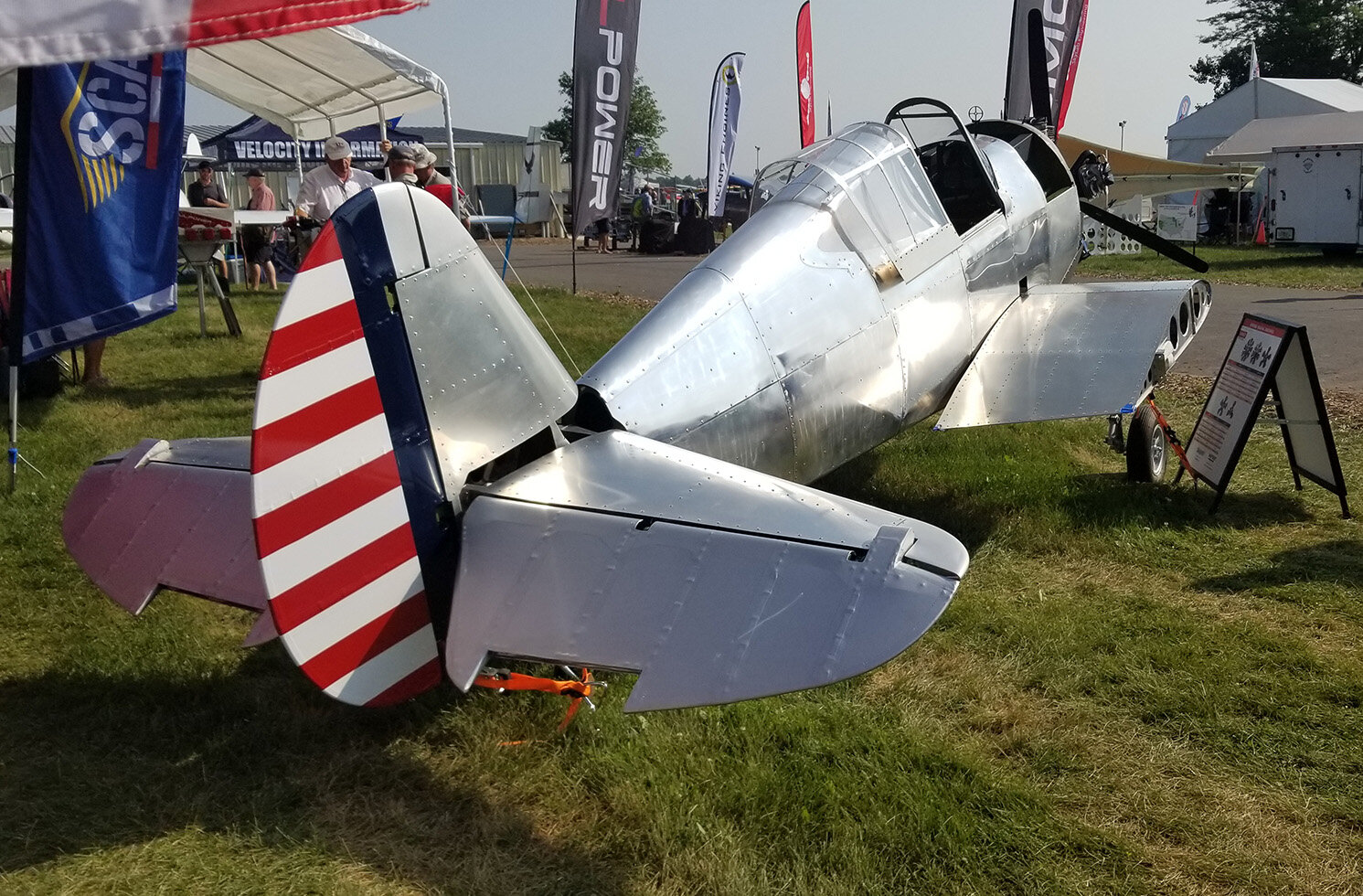
We then did all the same effort to the right - starboard wing. Mated the wing panels together, added the trailing edges. Made the tip bow and installed the ribs and spars. As I’m writing, Scott is fitting up the leading edge skins on the tip. The main top and bottom skins and tie-down are installed. Got to brush up on my english wheeling again to do that bottom skin piece. Hopefully this weekend we will be finished with the right wing. Then install the fuel tanks!

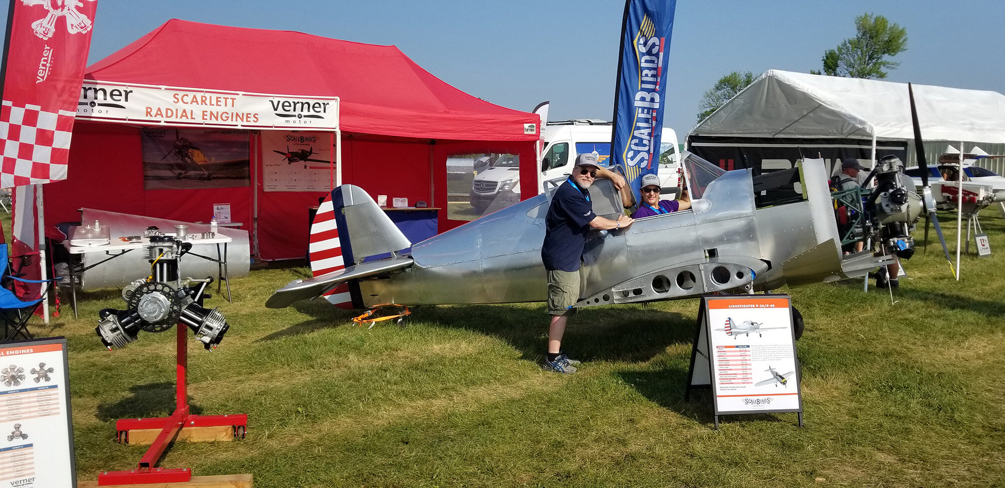
UPDATE: both wings are built. Second wingtip went well. We are very busy with engine mounts, exhausts and oil tanks for our Verner customers. One needed an adapter plate and Scott milled that out. Getting very frustrated with our UPS Customer Center - the procedures due to Covid. We are now starting to weld up the fuel tanks and have bent the capacitive senders as required for our installation. Can’t wait to see them installed and the wing back on the fuselage - shortly!

All of you - stay safe and keep plugging away at your projects.

p.s.: pictures coming shortly - check back. Down-load issue from our phones.

Different Times Indeed

Hey everyone. So far, 2020 isn’t what I was hoping for. We hope all of you are staying safe and healthy. We are doing our best. Sorry for all who are adversely affected by this pandemic and the economic response. These are different times indeed! Our thoughts and prayers for this nation, our first responders and defenders - and all of you. As many of you know, Sun N Fun 2020 has now been officially cancelled after being postponed. Oshkosh AirVenture 2020 is our next show and focus, that will not be decided until perhaps May. I’m sure the country needs to get back on its feet by June to make Oshkosh possible. Not sure about that - at this time. So many unknowns and decisions to come. For now, my team members are working our day jobs - all are critical defense infrastructure. The Navy wants it’s submarines without delay. We are still working on the ScaleBirds LiteFighter prototype - pretty much daily in fact. Here is a short update:

We had assembled the fuselage, tail and wing center-section up on gear in our new garage work studio. We then went to work making wing root and tail surface fairing templates from chip board for the metal panels and foam for the composite parts. We sent those templates off to our friends to be fabricated. We received them back and are super pleased with the results! We will trim and mount them later, after the next big job. We also finished assembling both our outboard wing panels in March. They are safely stored for now. We pulled the tail surfaces back off to add the trim tabs and mount the trim servo system in the elevator. Several steel brackets needed to be finish painted and permanently mounted. Done.

Our next big job is to remove the landing gear and wing center section from the fuselage. This is for installing the fuel tanks, filler necks, senders, fuel and lighting wiring, pitot hose and vent and fuel lines. To do this, we made a cradle to safely hold the fuselage at a good working level. At this point we are ready to remove the wing. That’s when all this virus stuff hit us here in CT. We stopped airframe work briefely to go through our systems and order everything we need to finish the aircraft for flight. We are still ordering parts and materials as I’m writing this. Aircraft Spruce is going to love us! I plan to work full time on the aircraft if I am forced to stay home. I want to err on the side of grabbing everything now while I can get it vs possibility of being stuck at home and not being able to get needed items. Just-in-case TSHTF! Its’ getting crazy here in CT. It’s also getting REAL - really fast!

We are ordering radios, instruments, electrical, fuel system items, brake hoses, engine controls and pitot static system components and materials. We are near 80% done with 80% to go! After these orders go out, we will pull the wing center-section and get to work. Will fill you all in along the way. We are planning to add more content and make some videos as we are putting the pieces together.

We are thinking about the paint/polish scheme some more. We were contacted by Chris Soltis, the curator for the Connecticut Air and Space Museum in Stratford, CT. He has us very intrigued about using the paint scheme for Rasmussen’s wing man during the Pearl Harbor attack response. Lt Gordon Sterling Jr. didn’t make it back from the dog fight. He was a Connecticut native and was given Distinguished Flying Cross for “conspicuous gallantry in the defense of Hawaii”. There are several historians and archivists digging for information. Most are concluding that the exact paint scheme is unknown - the four P-36’s were survivors they scrapped together from several squadron’s aircraft that were destroyed on the ground. Most agree that the aircraft had an Olive Drab and Grey paint scheme. All of the Army aircraft on Pearl were being re-painted to OD just before and at the time of the attack. We love the polished metal look but are seriously considering painting this replica in the olive drab scheme. We might keep the striped tail and not add the side fuselage roundel. There is at least one picture with that scheme from the time of the attack. Most of the aircraft had painted the rudder OD and added a roundel on the side of the plane. We want to honor Lt Sterling and also be eye catching. Will keep you posted. Thanks and Stay SAFE!

Great Expectations

Happy New Year everyone! We expect 2020 to be a great year for ScaleBirds LiteFighters and our Verner Motor dealership. We took advantage of holiday extended time off from the day job to get a lot done on the P-36 prototype. The ScaleBirds crew helped out a lot during the holiday break and we had them forming ribs, finishing the spars, forming the leading edge skins, fabricating the wing build fixture, and then drilling and deburring a lot of holes. We worked straight-out except for a few holiday parties and events. As of today - January 1, 2020, we are 90% done with the right outboard wing panel and all the parts for the left panel. We will have about 2 weeks into building the right panel and I hope about a week to do the left side. The second one always goes much faster. Figure everything out with the first and just assemble the second.

November saw us making slow and steady progress on the prototype. We worked on designing and making foam shapes for some of the fairings. Then, our good friend Rob Walty turned into beautiful composite parts which need hardly any finish work. We finalize the design of the oil and fuel tanks and cut parts. The oil tank is finished now and ready to install. We finished the design of the ailerons and converted everything over to 2D part files.

We were just about to start the wing build at Thanksgiving - when we decided that we needed to renovate the 2 car garage into a work space for the winter. This is hopefully going to make it more efficient to work on the whole project. Having all the parts and tools at my home facility instead of some here and some at the hanger, will allow work on multiple fronts and also prevent a lot of weather delays in Jan, Feb and March. So the last week of November and the first three of December were spent working on wiring, insulating, drywall, lighting, sheathing and siding my garage along with new windows, new doors, new garage doors. I now have a 9 ft ceiling and all LED lighting - very bright. We made provision for future propane heat but for now are using a portable propane heater. Works awesome with all the new insulation.

This also meant clearing out the garage of a lot of things I had stored in there. Well we completely filled a 20 yd. dumpster with the construction debris and unneeded household and shop items. I thought a 10 yard dumpster was almost big enough but opted for the larger one - glad I did! I highly recommend de-cluttering your shop/work space. Just do it!

January should entail finishing the wings and building the ailerons. More composite parts will be coming along. We will be assembling the fuel tanks and then installing them. Any down time will be filled with working on finishing touches on the airframe, instruments, controls, avionics. Stay tuned! Will post more often and more images and some video when it starts looking like something.

As I look back on 2019, we had some amazing events, adventures and experiences. We had tremendous Sun N Fun and AirVenture shows. We met some amazing people and gained new customers. We had fun with our current customers and are very thankful for them. We also had the tragedy of the 909 crash and some rough personal events. I am ready for a new year. A Great year! Come-on 2020!

Fall 2019 Update

Hi folks! We haven’t gone dark. Sorry, we just need to write more for you guys out there who are “living vicariously” thru us. I just wrote the report for the RFA magazine and had to write here too. Sorry if you end up reading almost the same thing in the magazine later. Anyway, we’ve had a very crazy few months of trips, visits, tragedies and small victories. We went to Ohio to Russ Turner’s WW1 bbq fly-in. Had to drive at the last minute as the Grumman AA5A Cheetah I share had a bad electrical glitch the day before. Ended up spending a lot of money on a new voltage regulator and rebuilt alternator. i’m still dealing with trying to get my Apollo GX60 GPS com radio fixed. Long drive, but since we were going to Dayton, we had to hit the Air Force museum and the Champagne Lady museum. Great trip! Our customer and good friend Steve Wolf came to visit as a co-pilot for the B-17 Nine O Nine in early September. Steve was in Connecticut for a week and flew the B-17 about 14 times. Waterbury Oxford and then right here at Groton New London airport. It was a treat to take Steve around our area. We never thought there would be a crash. The plane was meticulously maintained. Steve was home in Florida when the crash happened. It is such a tragedy. I’ve had a ride in Aluminum Overcast with the EAA and it was great to have my son and friend fly the 9O9 at our home airport with Steve Wolf at the controls with Capt. Mac. Will cherish those memories.

We redesigned the P-36 aileron controls and hinges from what we had modeled. This was to make them more like an RV-8 setup - even though ours are tapered. Something we thought we might do and it was time. We are making wing parts and getting ready to assemble the outboard wings. We are finishing the fuel system design and making parts. Firewall forward is getting worked on and we are ordering instruments and looking for radios. Our good friend and composites guru Rob Walty has a new moldless forming process and its working out super well. No more sanding out molds! We can mill foam or wood male or female plug on our 3D router table and he can go right to glassing up the part and vacuum bagging it without it sticking. The part pops right off and you can make as many as you want from the same shaped plug. Makes the exterior smooth like it was a polished mold. We will be doing the cowling, wing tips, tail fairings, gear leg fairings and wing root fillets in composite via this method. Our goal is to have the P-36 prototype ready to fly in time for SNF 2020. There will be delays, its inevitable, but we will push till this thing flies.


Verner Scarlett Radials FWF Corner: The Oil System

The Scarlett Engines have really been making a splash in the community over the last few years now, with their real radial sounds, the simple radial architecture, and the excellent performance we have seen from these round engines. Many classic aircraft designs only look right with a classic round engine shape on there, and only sound right when that engine is a real direct-drive radial.

As a result we’ve had numerous people asking us questions about installation options and how this engine might fit their birds, which often was designed for a different engine solution originally, and what needs to be changed. In general there’s 4 major things to consider: Engine Mount, Exhaust, Oil System, and Cowling/ducting. In the FWF corner, we’ll be giving overviews and eventually more detailed looks at the situations and solutions surrounding a Verner installation, whether you’re designing a new aircraft to take the engine, modifying a design, or retrofitting an existing aircraft to make the switch over to a Scarlett.

But today, after answering this question in detail for a potential customer, I decided it was only right to put this information out for everyone to see as I imagine for everyone who takes the time to send an email, there may be many more passively thinking about what they might do down the road. My hope is that over the next few months I can get enough information in this blog that it will be able to answer a lot of questions up front.

So onto the big concern for many who are considering the Verner, especially the replica builders:

The Scarlett Radial Oil System

The engines are designed as a pump supplied, gravity drained, dry sump to a remote reservoir type oil system. In other words no scavenging pump removes oil from the engine.

A mechanically driven pump mounted inside the front of the case draws oil up from the reservoir tank and forces it into the engine passages, before it finds its way through the engine and back to drain into the reservoir. Optionally an oil cooler may be installed in this loop.

There is a pair of main drain holes in the bottom of the case, as well as the drains from each of the valve covers of the lowest cylinders. The design intent for the engine, the purpose for the dry sump, is that in case of any pump or other mechanical failure, oil should always drain clear of the engine to prevent buildup and eventual hydraulic lock in operation. It is considered better by the Verners that a pump failure should simply deny the resupply of oil, in that a drained engine should still operate on residual oils for some window of time before an emergency landing, vs creating an oil flooded engine which could cease quite suddenly if not violently. While many successful engine designs have safely incorporated various oil scavenging systems, they generally come at increased cost, weight, complexity and so on. Verner subscribes more to the theory that if it's not there, it weighs nothing, costs nothing, and cannot fail. And if gravity fails, we have other issues.

Now, this is the theory they are operating under, and as explained to us. However, yes, many have asked about alternatives to the oil situation. And many would like to move the tank out of the way, which I appreciate. We can suggest it is physically possible for someone to incorporate their own system to move it higher, with various check valves and overflow valves to keep oil from building up inside the case and cylinders. However, as of now all of this is theoretical; the Verner company so far has stated they are not interested in incorporating such solutions at this time from the factory.

As dealers at ScaleBirds, we don't currently have the design or engineering experience with those types of systems where we can say what exactly is required or how to implement it beyond the scope of the original design from Verner. So we have not attempted any such systems and all of our customers have opted to find a way to incorporate a gravity fed tank solution. In most cases the tank is contoured to the bottom of the fuselage, and painted to match the scheme to blend it with the rest of the plane. We have worked with various customers on gravity drain oil solutions following Verner's criteria, and come up with what we think are some pretty good solutions at maintaining faithful appearances without having to invent any complex systems.


The absolute upper limit for tank placement, as told to us by Verner, is that when the aircraft is parked on its tailwheel with engine off: the level of oil in the tank should sit below the valve seats of the lowest cylinders. Now, they do prefer that the oil level sits a bit lower if possible, as in below the lowest intake and exhaust ports on the engine when the aircraft is level, but again the limit does allow a little tighter setup if required. Also while the tank requires some headroom for air space above the oil, that doesn't have to be in any particular proportion, it could be in the form of a tall funnel or an oddly shaped extension of some kind. Other suggested options have included moving the oil tank into the fuselage and running longer drain and pick-up hoses to the tank, making faux radiator scoops that are actually oil tanks, or even a small drop-tank or bomb shaped tank hung from the fuselage, with lines hidden up in the fuselage.

D8_3.jpg


Certainly all of these solutions are possible, but of course the best location is in front of the firewall and in a location easily accessible to check and fill the oil when the aircraft is parked. An oil tank that requires climbing under the aircraft or removing multiple components just to simply check the oil condition, is a solution more likely to go neglected.

For our replicas, we’re finding that many WWII aircraft luckily have ample cowlings and various vents and exit air ports in which we can easily fit a tank within the natural lines of the aircraft. However, we anticipate there will be cases where we are not so lucky, and in those situations we may have to do some creative work to integrate the tank geometry.

In any case, this is but one element of the overall picture, but I hope it has shined some light on the problem for those looking into the prospect of putting a Verner on their aircraft. Let us know if you have any particular questions, ideas, observations, or otherwise!

Tried and True

A little update as we are getting ready for Oshkosh 2019. Wow, time flies! Faster than most airplanes anyway. After SNF19, we had as our goal of building and testing our wing structure. This is what we have been doing for a while now. I always think things will go faster than they do. After a lot of effort, we did it! We had to build a wing and a test fixture as well. Our engineers crunched the numbers and developed a test regime. Our team successfully tested the wing panel to it’s design limit load of 4.4 g’s with no permanent deformation. We then tested her to design ultimate load of 6.6 g’s plus as much extra weight as we could scrounge. +300?? Measurements all along the way, but after the last loading there was about an 1/8” of permanent deflection in the spar and some slight wrinkles in the upper surface of the skin at the spar flange rivet line. Compression loads were crazy high during the test and you could see diagonal waves in the upper skin. Those were about a quarter inch to their crests. This was expected and within margins. Really cool tho! The test started after work around 5pm and went into the evening till about 8pm. Many hands makes for light work and we had a great crew. Lots of 40 pound gravel bags to put on and take off the wing multiple times. After the test was over we celebrated with champagne and beer (ok, some of the beer and pizza happened during the test). The wing panel weighed 31 pounds and held over 2800 pounds. Paul mentioned after the test - “we can lighten it!” I said, “lets up the g loading!”. As of now, we are working very hard to get to Oshkosh with as complete an airframe as possible. We removed the landing gear and the unfinished center section wing panel. Scott machined some of the internal landing gear components we needed to finish and I welded up the scissor link mounting lugs and misc. gear parts. After fit-up, they are ready to paint - this weekend. The center section unfinished wing has just been skinned and we are getting ready to re-install it. We will need to cut-out and drill the two major plates that join the two wings together at the centerline of the aircraft. Then ream the mounting holes to their final size on the aircraft. Our goal is to build at least one additional outboard wing panel for Oshkosh and have her back on gear and engine installed. Then as much detail as we can add in time. Since SNF, we also covered the rudder and elevators with silver Oratex fabric. I still have to rib stitch and tape the edges. I want to paint the rudder in red, white and blue stripes if we have time. We are pushing for it! Talk soon! Will add some pics from the test over the next couple days. Happy 4th! God Bless America!

Sun N Fun 2019

Hi friends. ScaleBirds attended the 2019 Sun N Fun airshow and had a great week. We had booth N68, right next to Viking aircraft engines. Our team pulled a lot of late nights and then all nighters to get the P-36 up on gear and to the show. We did it with no time to spare. We missed the setup day on Monday and arrived at 4:30am with the show starting at 9:00 am. Then, they wouldn’t let us in to set up till 8:00 am. Wasn’t expecting that, so we managed to have a minimal setup on Tuesday and then did the full setup after hours. Steve Wolf arrived Wednesday morning with SAMSONmite and we parked her up front and center. Our P-36 stood nearby and we had the red tent again thanks to Frank Johnson.

Our project was very well received. We are so stoked! Many commented how the lines looked right and that this was just the kind of next project they are interested in. We had the skins on the Port side of the wing center section and the exposed wing structure on the Starboard side. A lot of people liked that and made comments as to the construction method we are doing. Super positive responses from the engineers, DAR inspectors and experienced builders that stopped by. As well as the other airframe makers and engine builders too. That was a real boost to our engineers and to the build team. We are building it well and designing it right. It validated the decisions that were made two and three years ago.

We had so many people interested in the P-36 and P-40 variants. I think 50/50. The cool factor of the radial is a big seller. I would say we have a dozen very solid leads for a kit as soon as it is available. For other models, the crowd favorites at SNF are FW-190 and P-47. A Spitfire is in the running too. One lady was very interested in doing the Rufe after we have a Zero developed. She had a water rating and would love the Zero. A Rufe has never been replicated before as far as I know and I might just do it for that reason alone. But it would be really cool! Just think, we could have some fun and terrorize the seaplane base!

The Verner Motor engines are selling well and it’s starting to take on a business life of its own. WW1 replica builders and other antique aircraft builders/restorers are finally starting to pull the trigger after waiting for a couple years to see how these engines go. That is really great news as it helps us fund the project and gets some really cool airplanes into the air. We have a welder now and can make exhaust and mounting rings for the various engines. We had a couple engine mounts and various parts on display for people to pickup and check-out. I gave two forums at the education center building on the internal parts and main systems of a Verner engine. Very well received. Scott had to buy a laptop pc for the slide show to run on and then when we got there - didn’t work - wrong cable port. It turned out to be an IT project to find a student laptop that had the connection - and then to get the file downloaded with the content blocked by the school. Crazy stuff happens at SNF! Insert other choice words at your leisure. WE did have a good forum each time.

I will try to make a habbit of writing more blogs. I know many of you guys are interested. Will add pics over the next night or two. Tailwinds! - but not on take-off/landing.

Copyright © 2024 ScaleBirds LLC  |  All Rights Reserved