ScaleBirds

ScaleBirds, Home of the 63% Scale Hellcat replica kitplane project.

The Twist

Spring is trying to break through here in the Northeast, but not quite able to shake that winter chill. April just arrived and we have been working all of March on prepping for a new engine. Foremost was dealing with our landing gear. The third time I believe. This time, we had a nagging toe-in twist when the full weight of the aircraft was put to them. Studying it carefully, it was a combination of two things. The teflon liners inside the main tube had been relieved to allow the gear to easily slide with the spring motion. Well, we had given it too much clearance and that allowed the whole lower leg to pivot off center slightly. That little amount of sloppiness exacerbated the little bit of miss-alignment that I had welded-in on the scissor-links. Allowing the wheels to still toe-in a little bit. Barely noticable, but I don’t like it. One side slightly more than the other as well. Dang it!

After removing the engine to crate it for shipping to it’s new owner, we put the A frame back onto the engine mount and removed the landing gear. Scott studied the issue with the sleeves and ordered new teflon tubes. They arrived and were undersized on the ID. He then created a special reamer to take out the .010” all-around needed for the lower leg shaft to slide inside smoothly with no binding. The front of the reamer is the same as the id on the existing tube. Then he tapered out to the final ID we want and added cutting flutes. It worked, but clogged with chips quickly. Modifying this to allow the chips to exit also messed up the surface finish. Made a second reamer more like the original but shorter. This did a great job. It did take some time and careful drill work. We are just about done with the landing gear - again. We will be doing some careful milling and drilling of the scissor link upper mounting lugs to get them to track the wheels better. A little milling, a little paint, makes her what she aint. I am planning to get that done this first weekend in April in order to be able to put the gear back on and remove the A frame.

At the same time of working on the landing gear, we have been fabricating the fuel pumps panel assembly and installing it and the rest of the fuel hoses and tubing in the fuselage. It is 99% complete from firewall to the fuel tanks. Just one little thing left - adding the low point drain. That will be doable after we get the landing gear on and install the bottom skin and tunnel. Then, I can work from above the seat and below. Its a sequence thing.

Also have been working on the electrical system. Installing wiring and loom for fuel senders, landing and navigation lights. Made plywood mounting panel for the battery, solenoids and terminal blocks. They will fit up in the gun deck between the machine guns and on top of the forward fuselage frame bracing. I am finishing up the electrical schematic to know just how many switches and circuit breakers we will need a home for.

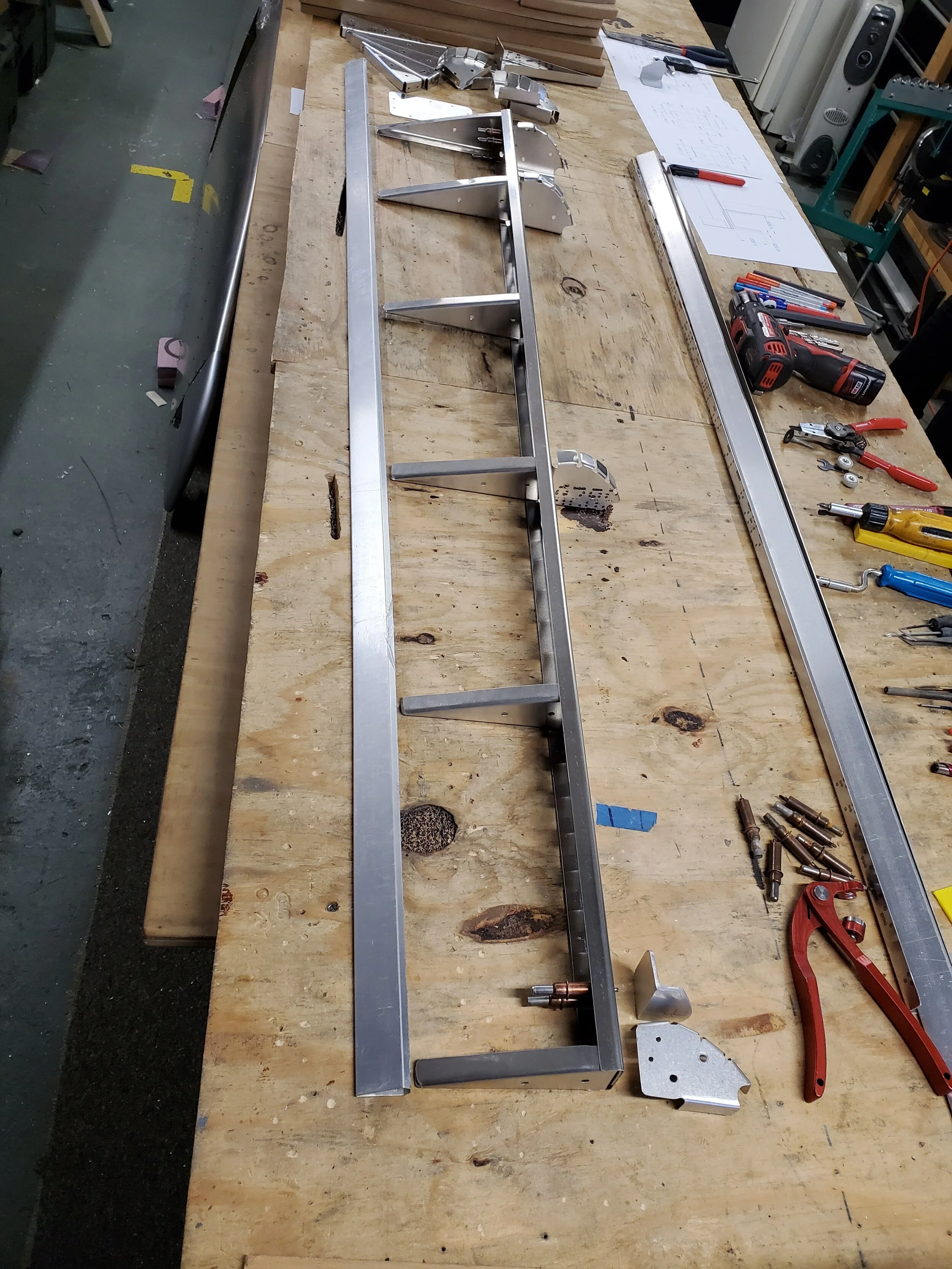
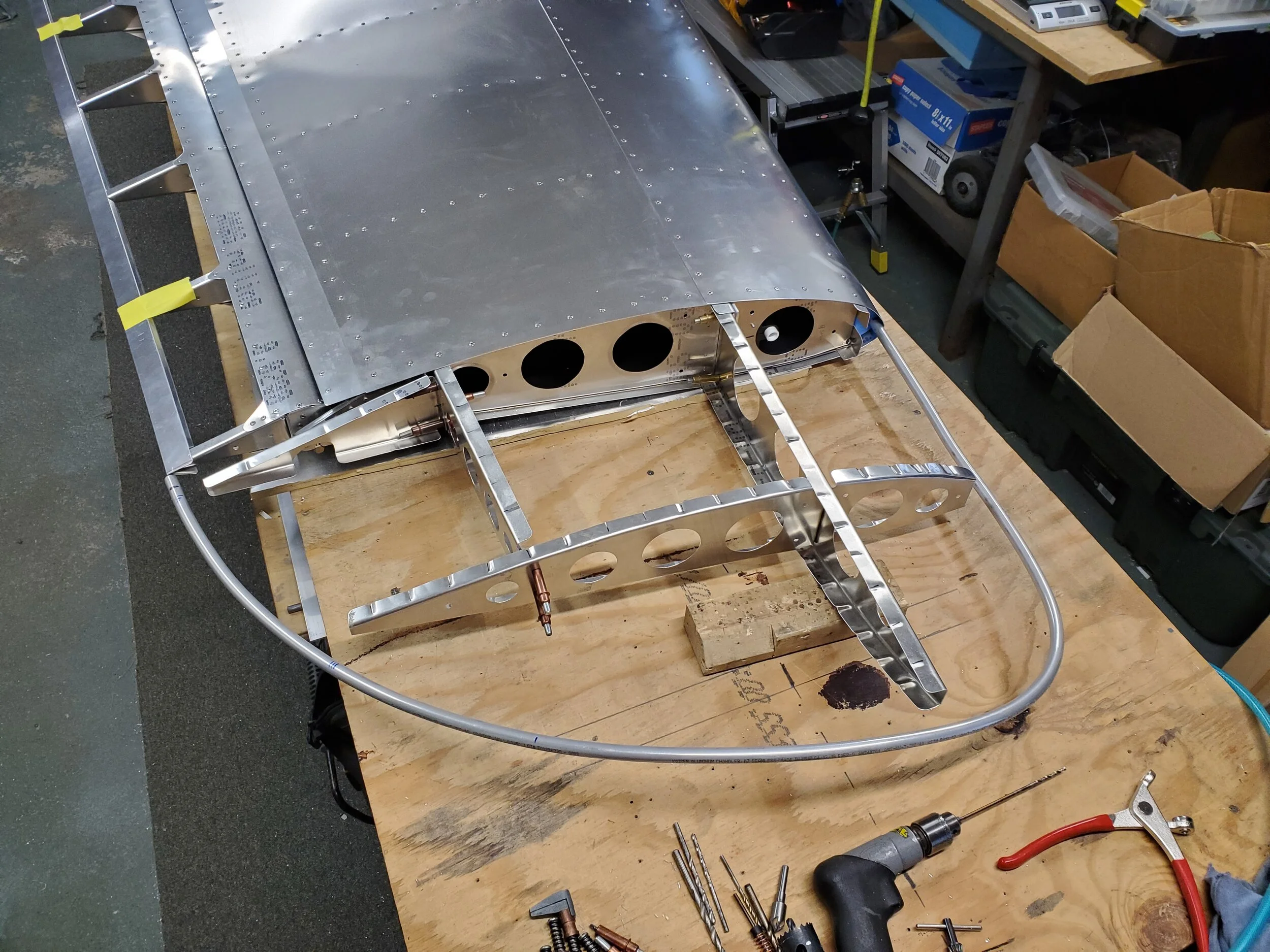
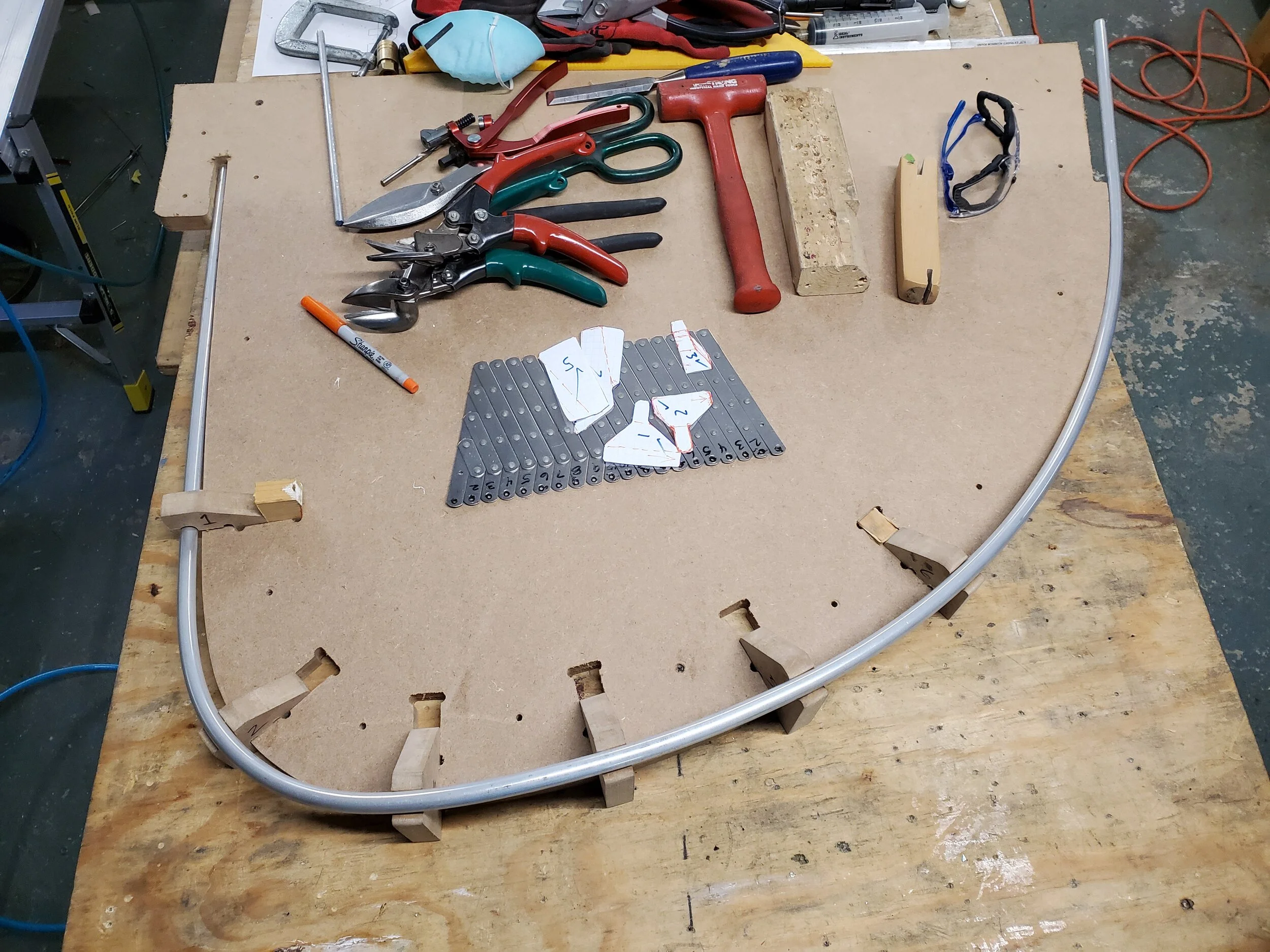
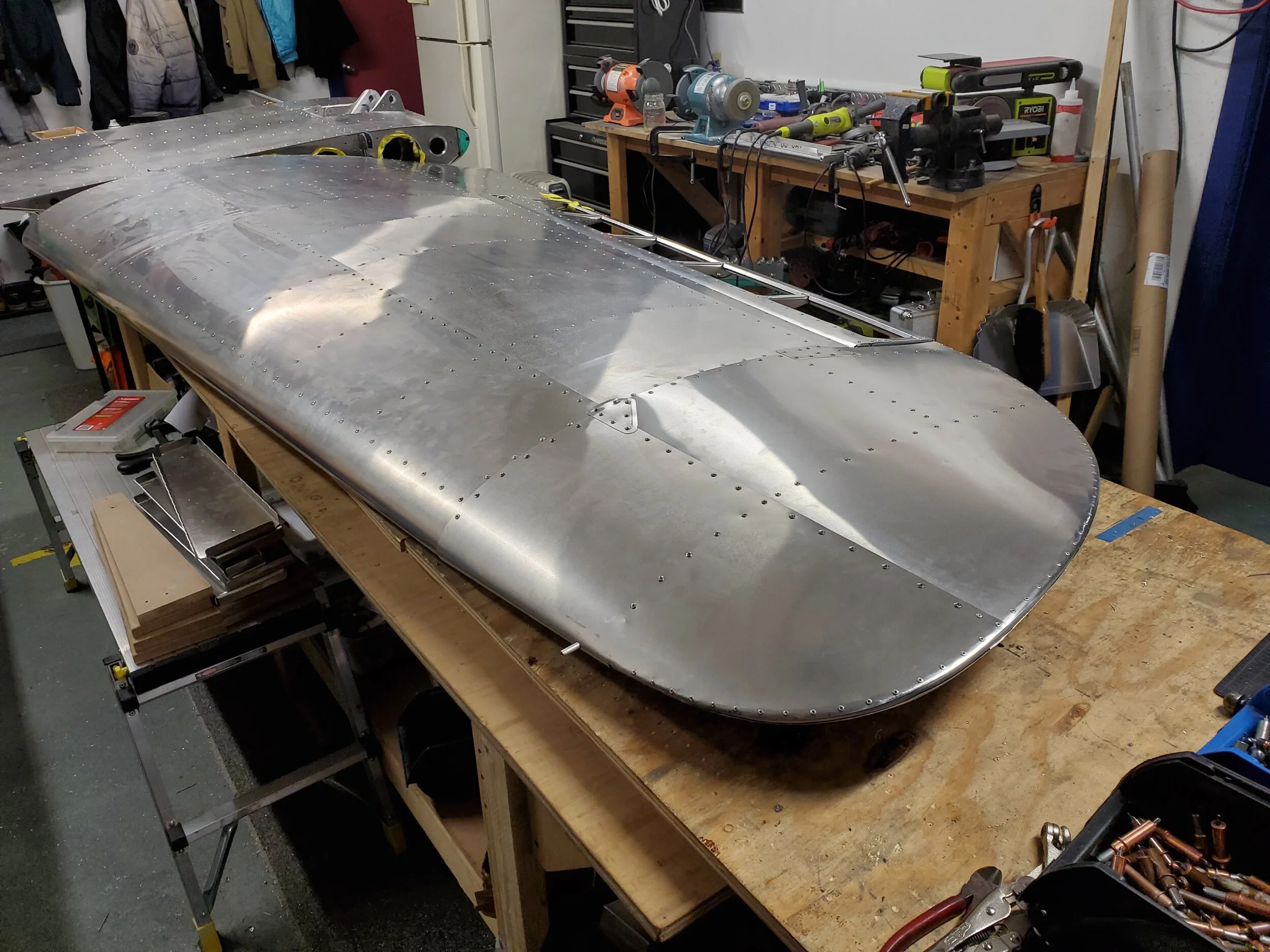
One more thing we have been working on is the tail and wing fairings. We had Jack Charles of Madison, WI English wheel our fairings for us. He was eager to try it - being a metal smith shop teacher for a high school and technical college. We sent him templates and descriptions of how much to roll and where. They came out very well. Excellent for only written descriptions and images. That is a tough thing to do and he did great! I trimmed and located the fiberglass trailing edge of the wing root fairings, drilling them when just where I wanted them. That plastic exterior painters tape did great for holding everything in place. The sheet metal fairing panels were then taped into location and adjusted as necessary. When good, I drilled and cleco’ed them to the wing and fuselage.

I used what seemed like a bunch of clecos to do it. I was kind of disgusted with my work thinking I had too tight of hole spacing, until I looked back at the reference photos. Curtiss had done the same thing on the real P-36. Lots of screws in the fairings and so ours looks right after-all. Back when we made the large trailing edge fiberglass pieces, we had made small fiberglass fairings for the leading edge of the wing where it gets seriously compound and tight. These were not the right shape after installing the sheetmetal fairing panels. The leading edge of the tail surfaces is another very tricky spot and we did not make a fiberglass piece for that. Thought about it long and hard and I want to try to pound out a soft annealed sheet metal leading edge. Ordered plenty of soft sheet and am about to get on that project. Getting those pieces done will allow me to finish the bottom section of the wing root fairings. Shouldn’t take too long. Adding the wing root fairings makes it look so much better! I can’t wait to paint them and see it with the wings and cowl.

Oh yah, Rob Walty made us our four quadrant cowling side panels and the nose bowl. We will be ready to start working on the cowl shortly. April and May will be really fun work!

We will be at Sun N Fun 2021 in a couple weeks. Our booth is in front of Building A and B along the main thoroughfare. Look up N68 on the exhibitor map. Sorry, we will not have the plane there. Way too close to flying to dismantle it and risk the trailer rash of hauling it both ways. We will have a brand new Verner Motor 9S radial engine on display. Our customer for that engine, Bob Beaty is #2 at the Sun ‘n Fun organization. He twisted my arm to have it on display. So after not planning to attend, we will. If you are going, please stop by and say hello. Love to talk with you. Then, right back to work right after we get back.

The Weighty Decision

Hey, since the end of January, we have been working up to where we are now. hahahaa! Of course! The landing gear was done and it was time to focus on systems. Such as the fuel system, electrical, oil, lights, etc. We installed the main fuel line in the fuselage from the selector valve to the firewall. Fabricated the selector valve mounting bracket and painted it. Made steel plugs for the firewall engine mounts to fireproof them as they pass behind the firewall. This allowed us to install the engine mount. We added the major components to the firewall as well (Ignition system, voltage regulator, air/oil separator, oil tank, the structural “tunnel”). We then decided to go ahead and mount the engine. We had to fabricate four spacers to move the engine 1/2” forward due to an error in the engine mount design which put one mounting puck support too close to an intake tube. This worked fine and we bolted the engine in place. Now we can look at the throttle installation and were all the systems and cables will route up forward. We had a cowling nose bowl that Rob Walty made for us and we had to fit it on the front. The sight lines are awesome!

Then, someone asked: “how much does it weight?” Well, that got us thinking, we really should do an in-progress weight and balance before we install everything - in case we need to move stuff. Well the wings were at the hangar and with the weather interfering, we needed to pick a good day to move the wings to the shop. We finally got a chance and brought them to the shop unscathed. Didn’t take us long to say - “ok, lets pin them on and see what she looks like”. Well they fit almost perfectly, but not quite. They had been assembled on the bench at the home shop, but we had replaced the inboard to outboard attachment brackets with more robust ones. Well, the more robust ones were a smidge too long and the inboard holes didn’t match the outbd holes. Scott spent a few hours filing the new brackets down to where the wings will fit together as intended. So we pinned the outboard wing panels onto the inboard ones and DANG! Looks like a fighter plane! We had finally achieved another milestone! We still need to drill and ream the holes to install the final bolts, but we have some other work to do first.

Back to the weight and balance, we did a relatively quick weighing of the plane on our bathroom scales. The weight seemed really good, 50 lbs under our target, but the balance was way off towards the tail. The whole thing felt fishy. Did some head scratching for a night or two, we then ordered better ‘industrial’ scales off of Amazon. Well as industrial as they can be for $40 each (They aren’t bad!) Importantly though, they have a digital readout display on a cable separate from the scale pad itself. We decided to try again with the hopefully more accurate scales. These new numbers showed us 90 pounds over our goal and still tail heavy. 90 pounds??? Turns out while bathroom scales can handle a decent amount of weight, they are designed to handle that from two feet standing on either side of the scale. Put all the weight in the middle and the plastic flexes… and bottoms out. Thus I can go on a serious 30lb diet just by changing my posture to a Flamingo stance! Jeeze, I thought that they may be cheap, but would only be off maybe 10 pounds or so. Nope! BEWARE! Even the new ‘Industrial’ scales showed a bit of flex from too much of a point load, so we decided to try and spread that more evenly on the scales.

So with some thick aluminum plates to distribute the load from the wheels, we rolled the plane onto the industrial scales: and at this point it was showing with the current engine, wings, structure, and all of that we are 775 pounds empty, with an aft CG which will only work with the lightest pilots. Ok, well we knew we were not building light and lean. We did not optimize this first-article’s structure for weight. This is a prototype and we know we can loose about 20-30 pounds with some design refinements, but we’ll definitely have to make sure to focus on that tail area next time. However, we also have been planning to at some point swap the engine for the heavier 7 cylinder Verner, or in-line auto conversions, such as the AeroMomentum AM15. Looks like now is a good time to do that!

The good news! The calculations show that with the Verner 7U or the AM15, or Viking 130, or basically any engine in the 200lb range, our empty center of gravity will be at 16% of our mean cord, with a total weight of approx. 829 pounds. A light pilot and low fuel is 22% cord and heavy pilot, full fuel and bags is 26% cord. A little heavier than planned (as is tradition it seems) but just about on par with published numbers for the RV-3, Panther, Onex, WAR Corsair and others, in terms of wing area, empty weight and hp. Each is a little different and we fit right in the middle of the lot. All told, we should have excellent performance!

So, which engine? We have been agonizing this bit over that for two weeks and they all have pluses and minuses for our project. We love radials! The 7U is an awesome engine with power and sound that just grabs everyone’s attention. We will be first to admit they can be a bit pricey. The AM15 is an excellent deal for price and power. Mark and the whole company are awesome to work with and they know their stuff. Most of our initial customers are going to want the P-40 model and we need to develop the firewall forward for it anyway. Sure, the reduction drive propeller shaft sits fairly low on the engine, and turns the “wrong” way; but that would still work for the early model P-40s (A, B, C) which is what this prototype is set up to be anyway. I have a lot of VW engine time so I and others like me are used to the p-factor being “wrong”. Then certainly it looks like the Viking 130 or even the new 150 would be options for the P-40E models and should have the power to make this aircraft perform. There seems to be plenty of options there. Some of the exhaust stuff on the P40 is going to be a bit of a tetris challenge to tackle, with getting the exits to all work. Radials aren’t immune to that either of course.

Of course, at the end of the day there was one obvious answer, and the only question was whether it could happen in time. We all want to see the P-36 fly, so we’re going to stick with the radial and get it flying as fast as possible. With our relationship with Verner, and the joy it would bring all to see our plane fly with a 7 cylinder on the nose, we talked with them and found a way to get a 7U within our timeframe. A toast for those guys for the effort they put into all of the engines and for taking care of us.

Of course, we need to still do a P-40 before there’s a riot; so the plan remains that we will do that, and use the auto engines for the next production prototype. On the next fuselage it will be a P-40E type, and will have all the improvements and lessons learned from the first go; including the retracts and a few other great adjustments to the lines. This version we will build concurrently with our early builders. And of course, for any P-40, we need to develop the engine mount, the exhaust headers, the radiator installation, the plumbing and cowling. Possibly utilize an inflight adjustable propeller as well. That will be a fun challenge - for later!

Keeping At It!

Greetings! Ok, so I am thrilled to report that we have the wing center-section installed and landing gear is down and locked. Fantastic! That bit of work took all of the weekend of the 16th, 17th (yes, I did get the bolts that Friday). Including a very late Sunday night work party. We got a little punchy, but had fun too, notice the image where Scott was trying on the Flinstone style landing gear! I want to thank all our crew for helping out and getting that done. Well done! This pushed us past our road block and allows us to progress on all systems and components. As evidence, this last week and weekend was a beehive of effort. Here is a short list of items we touched:

Completed the fuel vent lines and they are final. Installed Curtiss drains in the fuel tanks. Installed the seat harness after reinforcing the aft spar attachment brackets. Completed the pitot and static hose runs and connected to the instruments. Installed the oil tank. Adjusted the location of the fake 50 cal guns. Final fitment and adjustments to the tail wheel strut. Final install of the rudder cables and turnbuckles. Fixed the left main gear leg scissors - they had sloppy bushing holes and allowed too much movement of the tire. That job required us to remove the lower strut cylinder and machine new holes for larger bushings and bolts. That is complete and much better - though not perfect. Taxi testing will determine if we need to attack this again. We started to install the control stick assembly and hit a snag. The new larger bolts in the spar splice plates are too close to the mounting bolts for the stick assembly. We are designing a new mounting installation and will be fabricating that right away. We determined to add fiber-frax material aft of the firewall up to the first bulkhead - an issue we have been contemplating for a while. After we add that, we can close up the lower firewall with the bottom cowl components this week.

Been trying to decide what to do for the canopy latch. Images of the early model P-40 latches showed a weird base for the crank handle. After accidentally seeing one similar in an internet search for latches and hand cranks, I realized that Curtiss had used an accessory hand crank handle from a Singer sewing machine. The old hand crank they would use instead of foot operation and as a quick bolt-on accessory for doing bobbins (according to my daughter). I’m guessing this drove the chain drive for the canopy with a 3:1 gear ratio. So, I purchased one of these on-line and will go about modifying it and making new housing and cover plates with the idea of making a latch for the canopy, not a full-blown crank-it-open chain-drive like the original had. This is a simpler and lighter canopy.

This week we will finish installing the control column, begin the fuel delivery system, install the lower cowl and cooling tunnel, locate firewall components, battery box, install the tailwheel control cables, and the elevator control push tube installation.

She is starting to look like an airplane and looking good too! Can’t wait! Keeping at it! Click on the pic to see the next one.

The Waiting Game

Hey everyone. Not much to write about for the last two weeks. We have worked on the center-section fuel tanks. installed and sealed the fuel draw tube assemblies into their tanks. Installed the fuel sender units with neoprene gaskets instead of the cork ones that came with them. Routed the signal wires, pitot tubing and lighting wires through the wings and through the fuselage. Small but steady progress. The wing attachment blocks were installed and torqued, then marked with torque seal. We have the rudder cables mostly installed and need to work on the tailwheel steering cables. So, not a lot, but something.

Main reason for not getting a lot of progress is due to having to wait for hardware to arrive. We need to install the wing center-section and landing gear to proceed with all the systems. We ordered close tolerance bolts for the wing spar brackets, qty: 8. Well, Aircraft Spruce split the order and I was going to get 6 in three days and the other 2 in 12 days. Dang. well I waited the three days and got 5. Then I called and informed sales that they shorted me a bolt. Well they sent me one with free shipping. A week later, the two back-ordered bolts arrived. But not the shorted bolt. That took four more days to arrive by USPS in a small envelope. Weeks dealing with waiting for some bolts. Never been like that before with Spruce. They are not the lowest cost hardware, but reliable - they always have it and get it right out to you. Not now. Not sure why. Might be the same reason that all our local hardware and lumber stores have empty spaces on their shelves. End of year accounting.

Well, we finally had all the bolts and Scott finished up a bunch of paintball gun parts for his project. It was time to test fit the wing with the new blocks and hardware. Well, it fit perfectly - except the close tolerance bolts were barely fitting. After looking at it and checking the dimensions, I ordered a size that does fit -but not perfectly. The next size down would work perfectly. Arrrrgh! I waited for weeks! Well, ordered the new size bolts and had them shipped two day air.

So, been forced into a slow mode at the shop. Nice in some ways. But it’s Friday night and I’m waiting for the UPS driver to drop off my bolts. Today is the day! We will definitely get the wing on this weekend - when I can get the crew to show up. Will follow up with pics of it up on gear! Better go check the front door. See ya.

Tail of the Dog

Happy Holidays folks! Been working on the rudder installation now for weeks - among some other things - and I’m sick of it! The issue is some binding as all the bolts are tightened up. We’ve adjusted shims and played with tightening sequences to no avail. Some of the things we did helped, but nothing we have been doing is totally fixing it. So, after much frustration and quite a few cuss words, we’ve thought about the best way to make new hinges for this rudder. Unfortunately, we can’t replace the hinges completely unless we build a whole new rudder (that thought has crossed my mind). We do have a serious Haas mill at our disposal and it can make quick work of aluminum billet.

The issue: Prior to covering the rudder, we had decided to bring the airframe to Sun N Fun and Oshkosh. So we had to hurry and temporarily install the tail surfaces. Well, we never fully installed the rudder until now. The vertical was not perfectly located and the rudder post wasn’t meeting the aft fuselage frame at the same exact angle. So, when tightened, the rudder post had a very slight bow in it. This created a non-axial condition for the three hinges. Not an issue when snug, but an issue when fully tightened. The rudder would swing pretty nicely until bolted-up snug. Then it has some major binding and requires a bit of force to swing it. Leg strength on the rudder pedals could easily overcome it, but it isn’t acceptable.

Attempts to fix it: at first, we were excited to bolt it up for the first time with all the zeal of the plane “coming together”. Well that quickly faded as it was pretty heavily bound-up. Its an hour to install the rudder and about an hour to remove. Several of the bolts are almost impossible to get a wrench on. Well, maybe it is sequence, undo them all and tighten from side to side. Didn’t fix it. Ok, one more time another sequence. Nope. What the heck? Consternation and cussin’. Ok, uninstall, check the vertical for alignment. Not straight. Oh boy! So we checked and rechecked. The vertical was not correct - fore/aft due to the fwd spar being about 1/8” higher than designed and a smidge to far aft. This caused the top of the rudder post to be aft 1/8” as well. Ahhhh, that would do it. So we designed a fix for the vertical stabilizer’s fwd spar mount to the fuselage - which required some adapter plates due to new hole locations. Installed that and checked alignment. Beautiful. Ok, install the rudder and - still binding. Arrrgh! Well then we adjusted the shims at each of the hinges and re-installed the rudder each time. Nothing is working. Ok, check the rudder for straightness - it was built in a fixture so it should be. Yes, it is straight. What the heck?!? I finally gave-up entirely. Had to think about it. Thought about making a new rudder. Thought about palm trees and hammocks. Ok, back to reality! Fix this!!!

First, the hinge design is novel and we should have just done it like on an RV-8. But, this should work. Installing and removing the rudder is a total pain in the a##! Redo that for the production model for sure! We have a large mill, can we make a new rudder post from a solid billet? No, too heavy and would likely change the way the rudder aligns with the vertical. Sight lines would not be right. However, we can make new hinge receiver blocks that bolt up to the existing rudder post and can be individually adjusted at assembly. The existing hinges on the rudder just slide over the receivers and then we can drill and bolt the rudder independently from the side. Installing and removing the rudder would only take a few minutes and allows us to bolt all the structure together without having the rudder in the way. Easy access to the hardware and checking of alignment. That way we can adjust everything to be perfect before the rudder is installed.

Scott got busy after Christmas and modeled up the new receiver blocks and machined them out. They look awesome and fit perfectly. We installed them and tightened them up. The structure of the rudder post and vertical was now complete and we checked alignment - fully expecting to have to add shims. None were needed. Straight in all axis between all three receivers by like .010” or so. Well within our tolerance on the hinges themselves. We then attached the rudder to the vertical and the rudder slid right on - with just a little resistance. No binding at all. We drilled and pinned the hinge brackets to the receiver blocks and re-checked for binding - none! Wow! First time in weeks! We are super happy now with the rudder installation. Time to finish the rudder cables and tail wheel steering cables.

We also removed and remade new aft spar attachment brackets on each side of the fuselage. This will help with as built alignment of the wing spars to the fuselage and with the seat belt attachment area. Checks and double checks of the mounting alignment and tolerances showed we need to shave the front mounts by .050” to have the spars slide in perfectly. So we will do that over the next few days.

Static ports and hose is going in the aft fuselage. Wiring for tail lights and trim is going in. Our engineers Paul and Aaron worked on the bolt sizing calc for the spar. The calculations for the wing attachment brackets are complete and we are way strong - good to go for wing installation! Having to wait for two bolts of the 16 that are on back-order from Aircraft Spruce means we will not get the wing on this weekend, but will be able to by the end of the first week in January. Tough break, but we will not sit idle. On-ward!

12 Days to Christmas

Hello again to all our followers of the project. Very sorry for such a long delay in writing a blog. Have no fear! We are still super active and engaged in the P-36 Hawk build. The Covid-19 pandemic has caused us some issues with not meeting with all our crew. Major strain on everyone of you as well - I’m sure! We have also had some delays due to finding and moving into a facility. We needed space to assemble the prototype and a home for some very large machining equipment for ScaleBirds and Scott’s paint-ball gun company. That took way longer than we anticipated and we actually completely installed the equipment twice! The first time was in our two car garage and what a job that was! We quickly found that the electric service on our street is not living up to standards and barely good enough for residential - even though we installed a serious entrance to handle rated line amperage. The line was under-performing and old. So, either pay huge money to upgrade the street, or find a new home. We did the later and we have a tremendous new facility at the local airport industrial park. We still had to un-install, relocated, install all over again and then improve the space with bathroom and air compressor rooms. We have added benches, desks, tables, tool boxes, storage racks, electrical receptacles for work stations as well as a fridge and microwave. I need a coffee maker for Christmas (honey are you listening?). It’s a great shop and the landlord is a private pilot and giving us a super deal. Thank you Kevin Cook! We now have a commercial address - still need to get the mail setup - so we will be able to have customers stop by and not have to deal with my home basement. We will still be fabricating parts and designing from home - I have a great shop there with suddenly more space in it.

Prior to all the equipment/shop effort, we prepped and painted the whole airframe in August. We were under-the-gun so we didn’t have time to blog about it - then jumped right into the machine space prep and install. No time either as that situation turned into a serious major catastrophe and then back to a super exciting and awesome ending.

The current situation - 12 days to Christmas: The airframe is mostly at the new shop. Wings and engine are in our hanger space. We have the fuselage in a temporary stand mounted to the engine mount and resting on the tail wheel. The wings are removed. We have installed the canopy, instrument panel and tail surfaces. We have replaced the wing attachment brackets with billet machined plates. We installed the fuel tanks and closed-up the inboard wing sections. This week we are replacing the aft spar to fuselage brackets prior to installing the wing center-section by Christmas hopefully. We are also chasing a little binding issue with the rudder - we have nailed that down to the vertical stabilizers’ fwd spar attachment. We are designing a simple fix and will get that ironed out in a few days.

We will have some extra hands on deck with the Christmas to New Years week off from the day job. The plan is to have the airframe out of the fixture and standing on its gear legs with the engine re-attached. Flight controls installed again and rigged by end of the year. Early January should be wiring, pitot, fuel and brake lines. Then fairings and cowling installation. We will be making a very concerted effort to keep you all better informed and show more pics and some videos. Scott has been posting images to Instagram and Facebook. Its really getting exciting now that it has paint and is coming back together! The end is in sight - and that’s only the beginning!

Steady as She Goes

It is about time we got to another blog entry. As always - way late. The Covid virus has had its impacts on our project - delays with shipping and vendors, etc... Gladly, no one on our team has contracted the virus - that we know of. It has prevented the whole team from getting together to work on the project. Mostly it’s just Scott and myself working on the physical parts. Slow going, but progress has been made. I am working the day job from home - super unusual for defense work. It gives me about an extra hour a day to work on the project. I’ll take it!

After building the rack for the fuselage, we removed the wing center-section and landing gear. Then, one wing half at a time, we mated the outboard wing to that sides’ inboard wing panel. They mated-up almost perfectly - thanks to CAD and CNC mfg. We only needed to remove a little bit of spar web that we left long for some reason - we don’t think of everything first time around! The spar caps and mounting brackets fit together like a glove. That allowed us to finish the trailing edges of the outboard wing and the aileron - aligning them with the inboard panel’s trailing edge. We started with the port - left - wing first. after finishing the aileron, we went into working on the wing tip.

The wing tips were originally going to be composite and just bolted and riveted on. Easy peezy! Well, problem is we were going to be a long time getting them - our buddy switched to making masks and face shields for first responders. Good cause for sure! But it is another major delay we are dealing with. So we thought about it. The real one is metal. Can we do it? After studying the real P-36 wing tip design and the P-40B that we had close-up images of, we decided that we could do a decent job of making it from metal - if we can english wheel a small panel on the bottom leading edge. Another way would be to hydro-form the piece. Turns-out, Curtiss designed the wing tip shape to work with the airfoil - almost all of the top surface and more than half the bottom surface line up with a 3D shaped tip bow and readily lay right down onto the bow. We just had to round the outboard edge to lay against the bow and rivet in place. Hand pounding along a curved steal mandrel worked well. To do the very curved bottom leading edge piece, we purchased a small, vice mounted english wheel and spent some time playing with shaping scraps. Well, it is not easy, but we taught ourselves to wheel soft aluminum sheet. YouTube videos helped. Much better equipment would also help. This was relatively inexpensive and small - it does not take up valuable floor space in our shop - we don’t have any to spare! You get what you pay for though - its much rougher wheel paths, but it did work well enough I think for sanding and painting the tips - not quite good enough for polished metal finishes.

We fabricated the wing tip bows from 3/8 tubing and bending around a wood form. Then added 3D shape to it with wood jigs at various stations along the bow. Hand forming the bow to shape. In and out of this fixture a bunch of times before having it sit perfectly in place. Then we fitted the ribs and short spars parts that make up a support frame for the tip. That’s when we worked the skins and drilled, riveted them in place.

After fitting the last of the left wing tip skins, Scott wanted to make spring retractable tie-down rings - per Curtiss. He designed them to be very similar to the original, but easy to fabricate with our equipment. He also had to design a welding and milling fixture that worked really well. I welded the rings to the print and Scott cleaned them up and added holes on the mill. Then he cut the aluminum mounting bracket on the mill and installed everything. I think they turned-out awesome!

The left wing also gets the pitot mast and head. On most of the early WW2 aircraft, the pitot head was this large spear with a shark fin. We looked at machining it - very serious machining and decided against it. 3D printing was a good option. Scott’s friend is now president of a 3D printing company doing amazing parts for medical and defense customers. He printed our design up on a state of the art printer. It came out looking like it was cast. Just the slightest surface grain - like a #2 mold surface. It’s dark grey plastic resin but can be painted. I fabricated the mount that holds the mast and head to the leading edge. Scott made a bulkhead mount for the 1/4” aluminum tube to pass through the spar web where we wanted it to be. After installing the mount, we could close up the wing tip for good. Each wing tip has a generous access panel for getting to wiring and pitot components. So then we riveted the skins on. Wing done! I think it came out awesome for not being experienced metal craftsmen. And looking at the pictures, the originals were not perfect. Today, the restoration shops are paid millions and make everything perfect and then polished or gloss painted. Back in the day, they were slamming them out as fast as they could.

We then did all the same effort to the right - starboard wing. Mated the wing panels together, added the trailing edges. Made the tip bow and installed the ribs and spars. As I’m writing, Scott is fitting up the leading edge skins on the tip. The main top and bottom skins and tie-down are installed. Got to brush up on my english wheeling again to do that bottom skin piece. Hopefully this weekend we will be finished with the right wing. Then install the fuel tanks!

UPDATE: both wings are built. Second wingtip went well. We are very busy with engine mounts, exhausts and oil tanks for our Verner customers. One needed an adapter plate and Scott milled that out. Getting very frustrated with our UPS Customer Center - the procedures due to Covid. We are now starting to weld up the fuel tanks and have bent the capacitive senders as required for our installation. Can’t wait to see them installed and the wing back on the fuselage - shortly!

All of you - stay safe and keep plugging away at your projects.

p.s.: pictures coming shortly - check back. Down-load issue from our phones.

Different Times Indeed

Hey everyone. So far, 2020 isn’t what I was hoping for. We hope all of you are staying safe and healthy. We are doing our best. Sorry for all who are adversely affected by this pandemic and the economic response. These are different times indeed! Our thoughts and prayers for this nation, our first responders and defenders - and all of you. As many of you know, Sun N Fun 2020 has now been officially cancelled after being postponed. Oshkosh AirVenture 2020 is our next show and focus, that will not be decided until perhaps May. I’m sure the country needs to get back on its feet by June to make Oshkosh possible. Not sure about that - at this time. So many unknowns and decisions to come. For now, my team members are working our day jobs - all are critical defense infrastructure. The Navy wants it’s submarines without delay. We are still working on the ScaleBirds LiteFighter prototype - pretty much daily in fact. Here is a short update:

We had assembled the fuselage, tail and wing center-section up on gear in our new garage work studio. We then went to work making wing root and tail surface fairing templates from chip board for the metal panels and foam for the composite parts. We sent those templates off to our friends to be fabricated. We received them back and are super pleased with the results! We will trim and mount them later, after the next big job. We also finished assembling both our outboard wing panels in March. They are safely stored for now. We pulled the tail surfaces back off to add the trim tabs and mount the trim servo system in the elevator. Several steel brackets needed to be finish painted and permanently mounted. Done.

Our next big job is to remove the landing gear and wing center section from the fuselage. This is for installing the fuel tanks, filler necks, senders, fuel and lighting wiring, pitot hose and vent and fuel lines. To do this, we made a cradle to safely hold the fuselage at a good working level. At this point we are ready to remove the wing. That’s when all this virus stuff hit us here in CT. We stopped airframe work briefely to go through our systems and order everything we need to finish the aircraft for flight. We are still ordering parts and materials as I’m writing this. Aircraft Spruce is going to love us! I plan to work full time on the aircraft if I am forced to stay home. I want to err on the side of grabbing everything now while I can get it vs possibility of being stuck at home and not being able to get needed items. Just-in-case TSHTF! Its’ getting crazy here in CT. It’s also getting REAL - really fast!

We are ordering radios, instruments, electrical, fuel system items, brake hoses, engine controls and pitot static system components and materials. We are near 80% done with 80% to go! After these orders go out, we will pull the wing center-section and get to work. Will fill you all in along the way. We are planning to add more content and make some videos as we are putting the pieces together.

We are thinking about the paint/polish scheme some more. We were contacted by Chris Soltis, the curator for the Connecticut Air and Space Museum in Stratford, CT. He has us very intrigued about using the paint scheme for Rasmussen’s wing man during the Pearl Harbor attack response. Lt Gordon Sterling Jr. didn’t make it back from the dog fight. He was a Connecticut native and was given Distinguished Flying Cross for “conspicuous gallantry in the defense of Hawaii”. There are several historians and archivists digging for information. Most are concluding that the exact paint scheme is unknown - the four P-36’s were survivors they scrapped together from several squadron’s aircraft that were destroyed on the ground. Most agree that the aircraft had an Olive Drab and Grey paint scheme. All of the Army aircraft on Pearl were being re-painted to OD just before and at the time of the attack. We love the polished metal look but are seriously considering painting this replica in the olive drab scheme. We might keep the striped tail and not add the side fuselage roundel. There is at least one picture with that scheme from the time of the attack. Most of the aircraft had painted the rudder OD and added a roundel on the side of the plane. We want to honor Lt Sterling and also be eye catching. Will keep you posted. Thanks and Stay SAFE!

Copyright © 2024 ScaleBirds LLC  |  All Rights Reserved