Verner Scarlett Radials FWF Corner: The Oil System
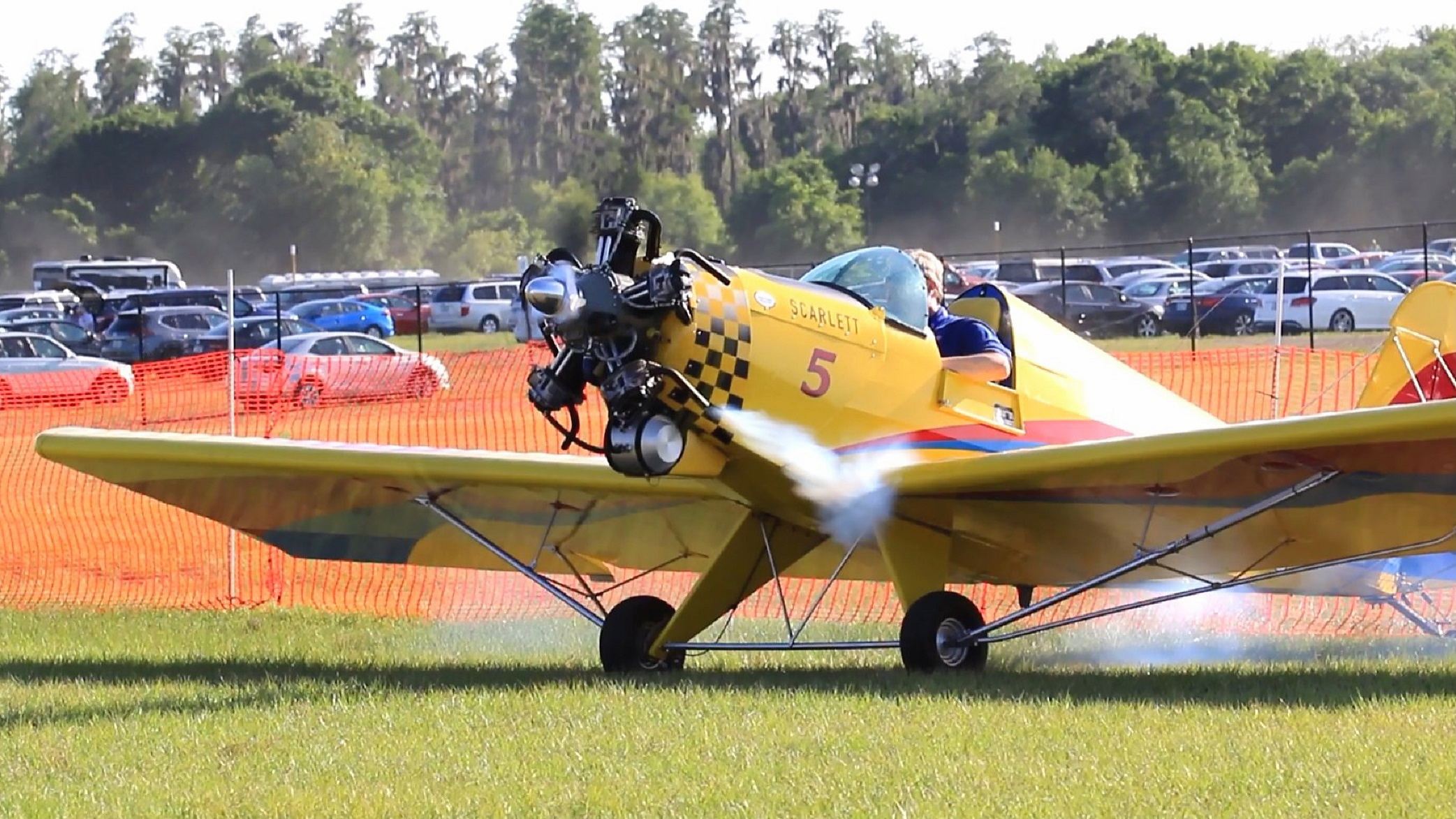
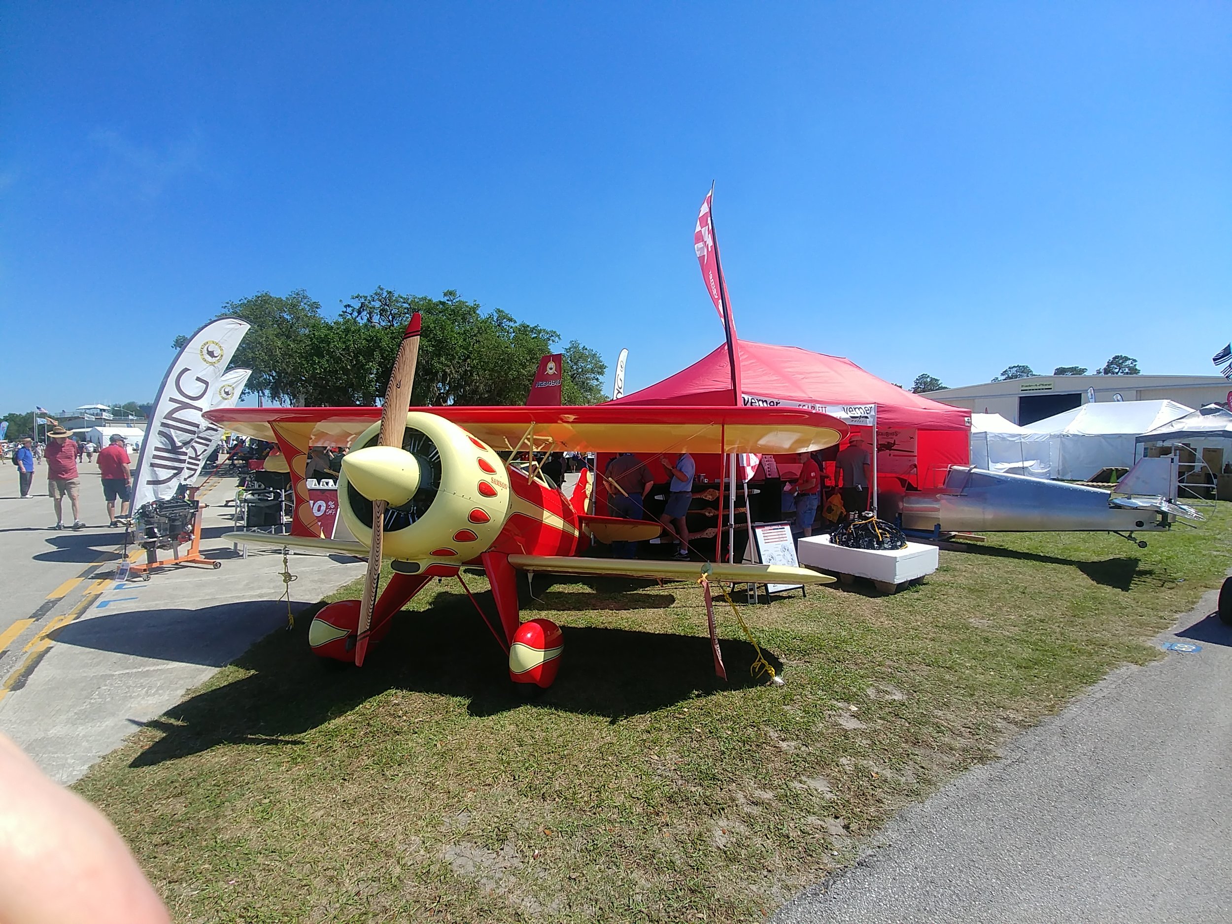
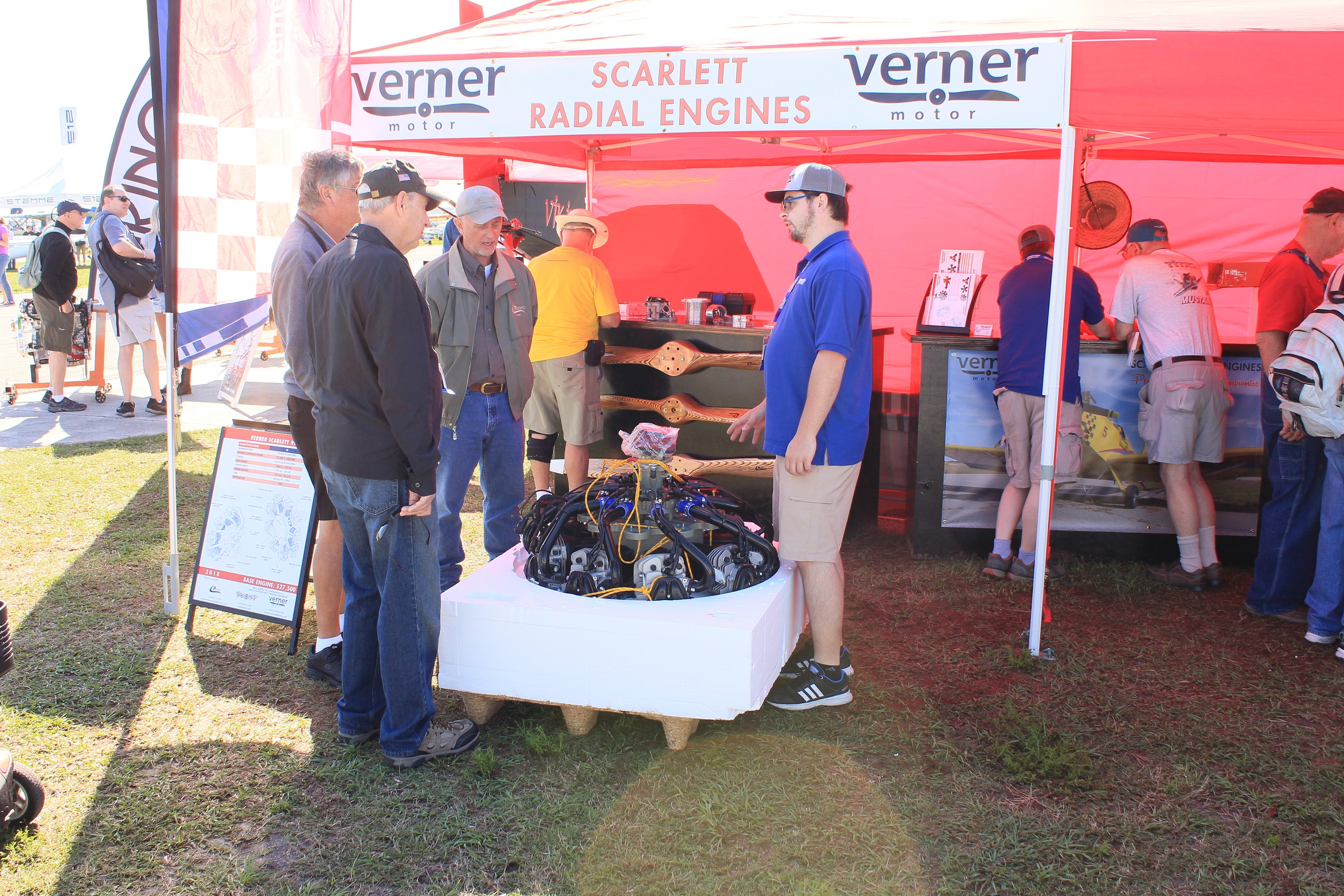
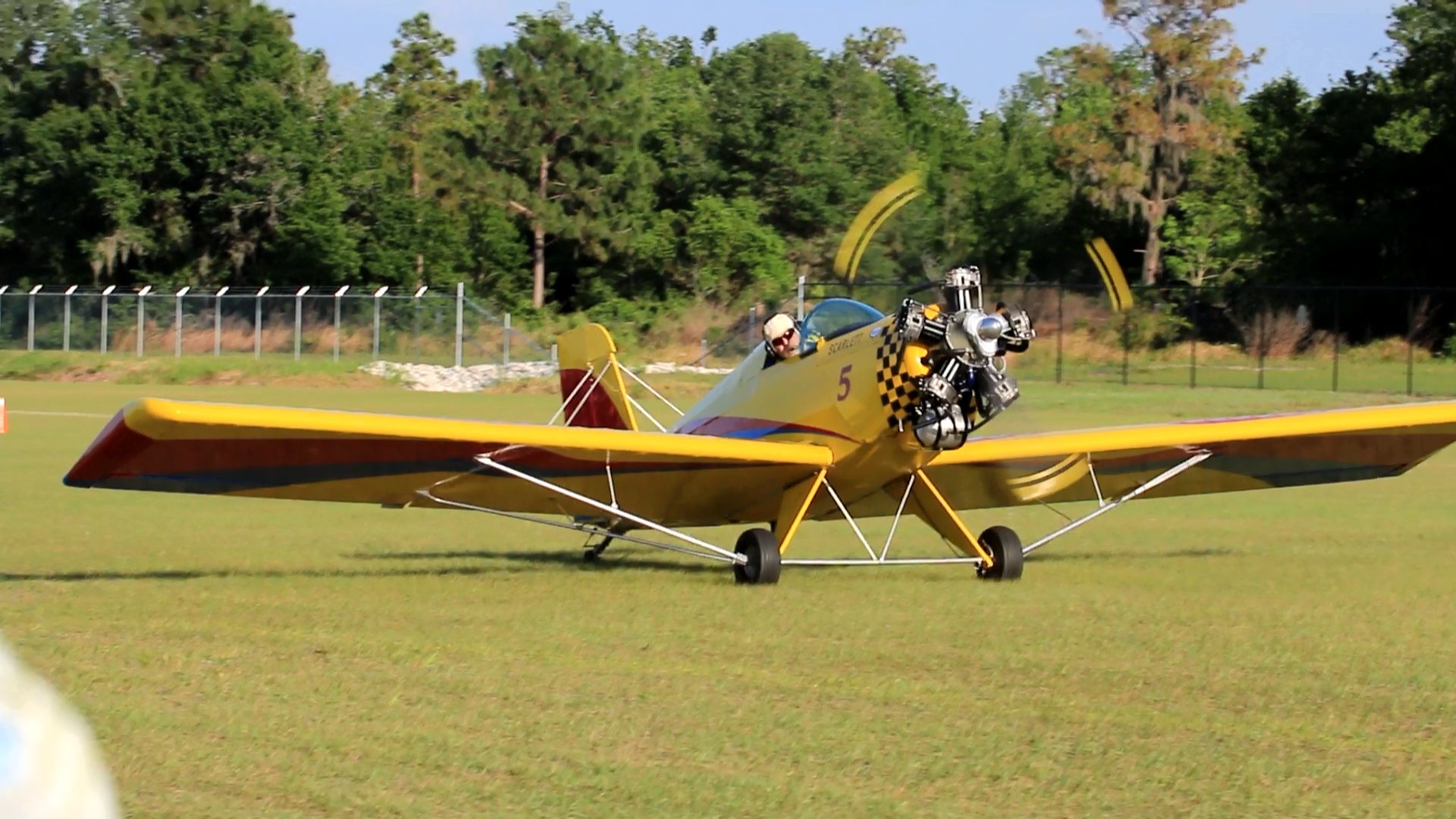
The Scarlett Engines have really been making a splash in the community over the last few years now, with their real radial sounds, the simple radial architecture, and the excellent performance we have seen from these round engines. Many classic aircraft designs only look right with a classic round engine shape on there, and only sound right when that engine is a real direct-drive radial.
As a result we’ve had numerous people asking us questions about installation options and how this engine might fit their birds, which often was designed for a different engine solution originally, and what needs to be changed. In general there’s 4 major things to consider: Engine Mount, Exhaust, Oil System, and Cowling/ducting. In the FWF corner, we’ll be giving overviews and eventually more detailed looks at the situations and solutions surrounding a Verner installation, whether you’re designing a new aircraft to take the engine, modifying a design, or retrofitting an existing aircraft to make the switch over to a Scarlett.
But today, after answering this question in detail for a potential customer, I decided it was only right to put this information out for everyone to see as I imagine for everyone who takes the time to send an email, there may be many more passively thinking about what they might do down the road. My hope is that over the next few months I can get enough information in this blog that it will be able to answer a lot of questions up front.
So onto the big concern for many who are considering the Verner, especially the replica builders:
The Scarlett Radial Oil System
The engines are designed as a pump supplied, gravity drained, dry sump to a remote reservoir type oil system. In other words no scavenging pump removes oil from the engine.
A mechanically driven pump mounted inside the front of the case draws oil up from the reservoir tank and forces it into the engine passages, before it finds its way through the engine and back to drain into the reservoir. Optionally an oil cooler may be installed in this loop.
There is a pair of main drain holes in the bottom of the case, as well as the drains from each of the valve covers of the lowest cylinders. The design intent for the engine, the purpose for the dry sump, is that in case of any pump or other mechanical failure, oil should always drain clear of the engine to prevent buildup and eventual hydraulic lock in operation. It is considered better by the Verners that a pump failure should simply deny the resupply of oil, in that a drained engine should still operate on residual oils for some window of time before an emergency landing, vs creating an oil flooded engine which could cease quite suddenly if not violently. While many successful engine designs have safely incorporated various oil scavenging systems, they generally come at increased cost, weight, complexity and so on. Verner subscribes more to the theory that if it's not there, it weighs nothing, costs nothing, and cannot fail. And if gravity fails, we have other issues.
Now, this is the theory they are operating under, and as explained to us. However, yes, many have asked about alternatives to the oil situation. And many would like to move the tank out of the way, which I appreciate. We can suggest it is physically possible for someone to incorporate their own system to move it higher, with various check valves and overflow valves to keep oil from building up inside the case and cylinders. However, as of now all of this is theoretical; the Verner company so far has stated they are not interested in incorporating such solutions at this time from the factory.
As dealers at ScaleBirds, we don't currently have the design or engineering experience with those types of systems where we can say what exactly is required or how to implement it beyond the scope of the original design from Verner. So we have not attempted any such systems and all of our customers have opted to find a way to incorporate a gravity fed tank solution. In most cases the tank is contoured to the bottom of the fuselage, and painted to match the scheme to blend it with the rest of the plane. We have worked with various customers on gravity drain oil solutions following Verner's criteria, and come up with what we think are some pretty good solutions at maintaining faithful appearances without having to invent any complex systems.
The absolute upper limit for tank placement, as told to us by Verner, is that when the aircraft is parked on its tailwheel with engine off: the level of oil in the tank should sit below the valve seats of the lowest cylinders. Now, they do prefer that the oil level sits a bit lower if possible, as in below the lowest intake and exhaust ports on the engine when the aircraft is level, but again the limit does allow a little tighter setup if required. Also while the tank requires some headroom for air space above the oil, that doesn't have to be in any particular proportion, it could be in the form of a tall funnel or an oddly shaped extension of some kind. Other suggested options have included moving the oil tank into the fuselage and running longer drain and pick-up hoses to the tank, making faux radiator scoops that are actually oil tanks, or even a small drop-tank or bomb shaped tank hung from the fuselage, with lines hidden up in the fuselage.
Certainly all of these solutions are possible, but of course the best location is in front of the firewall and in a location easily accessible to check and fill the oil when the aircraft is parked. An oil tank that requires climbing under the aircraft or removing multiple components just to simply check the oil condition, is a solution more likely to go neglected.
For our replicas, we’re finding that many WWII aircraft luckily have ample cowlings and various vents and exit air ports in which we can easily fit a tank within the natural lines of the aircraft. However, we anticipate there will be cases where we are not so lucky, and in those situations we may have to do some creative work to integrate the tank geometry.
In any case, this is but one element of the overall picture, but I hope it has shined some light on the problem for those looking into the prospect of putting a Verner on their aircraft. Let us know if you have any particular questions, ideas, observations, or otherwise!


